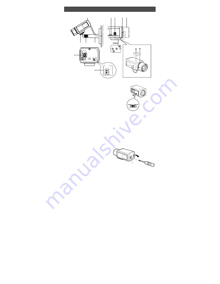
q
w
e
r
t y
i
!0
u
o
!1
ALC
BLC
OFF ON
ELC
ALC NC ELC
ALC
BLC
OFF ON
ELC
MAJOR OPERATING CONTROLS AND THEIR FUNCTIONS
q
Camera Mounting Bracket
Install on the wall or ceiling. See INSTALLING
PROCEDURE below.
w
Pan Fixing Ring
Tighten after adjusting the pan angle.
e
Pan Head
Attach the camera on this.
r
Auto Iris Lens Connector
Supplies power and DC control signals to an
auto iris lens (not supplied).
t
Flange-back Adjusting Ring
This ring adjusts the back-focal distance or
picture focus.
y
Lens (option)
u
Camera Mounting Adapter
There is a hole for mounting the camera onto
a mounting bracket. The camera is originally
designed to be mounted from the bottom, but
a top-mounting type is also available. To
mount from the top, remove the mount
adapter from the bottom of the camera by
removing two fixing screws. Attach the mount
adapter to the top as shown in the diagram,
then mount the camera on the mounting
bracket. Make sure that two original screws
are used when mounting the mount adapter;
longer type screws may damage inner com-
ponents.
i
Lens Selector
Detach the cover from the camera and select
the mode according to the lens type that is
mounted on this camera.
ALC:
Select this mode when an auto iris lens
(ALC lens) is mounted on this camera.
NC:
Not used.
ELC:
Select this mode when a fixed iris lens
or manual iris lens is mounted on this
camera.
!1
Back Light Compensation Mode Selector
(BLC ON, OFF)
Select the mode according to the position of
the object and light conditions.
When the ALC lens is mounted on this cam-
era, select the mode with upper selector.
When the fixed iris or manual iris lens is
mounted, select with the lower selector.
ON:
Select this mode when a strong light
such as a spotlight is in the background.
OFF:
Normal picture.
o
Coaxial Cable Connector
Connect a coaxial cable (to be procured
locally) between this connector and the CAM-
ERA IN connector of the specific monitor (or
Camera Drive Unit).
Monitor supplies power to the camera, and
the camera supplies the video output to the
monitor through the coaxial cable.
!0
Rear Cover
The rear cover can be removed to gain
access to the switches.
ALC NC ELC
Rear Cover


