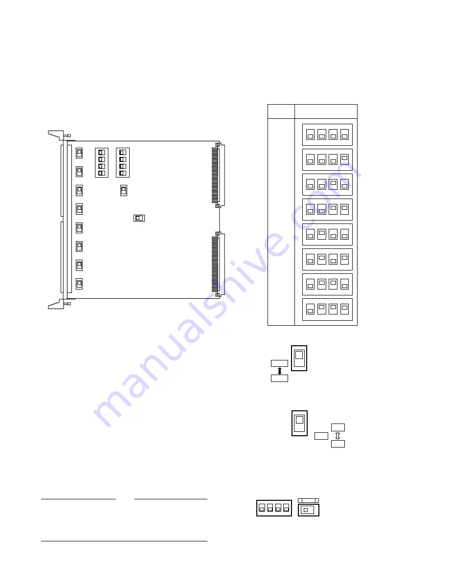
BOARD SETTING
Before installing this board, the following settings should be made by qualified service personnel or system installers.
1234
OFF
SW1
1234
OFF
SW3
SW100
SW150
SW200
SW250
SW300
SW350
SW400
SW450
SW5
SW6
BOARD
NO.
1
2
3
4
OFF
1
2
3
4
OFF
1
2
3
4
OFF
1
2
3
4
OFF
1
2
3
4
OFF
1
2
3
4
OFF
1
2
3
4
OFF
1
2
3
4
OFF
1
2
3
4
5
6
7
8
SW1 SETTING
1. Set switches (SW1) on the board to meet the data
board number as shown in the following table.
Initially, board number 1 is selected at the factory.
2. Set switches (SW100/SW150/SW200/SW250/SW300/
SW350/SW400/SW450) on the board to choose the
communication lines as either Full Duplex (FULL) or
Half Duplex (HALF).
Initially, Full Duplex(FULL) positions are selected at
the factory.
3. Set switch (SW5) on the board to choose the LED indi-
cator as either “ON” or “OFF” mode. The indicator dis-
plays that the control data are activated normally on
the board.
Initially, “ON” position is selected at the factory.
4. Confirm switches (SW3/SW6) on the board are set to
the following positions.
SW100 - SW450
FULL
HALF
SW5
ON
OFF
LED
1
2
3
4
OFF
SW3
SW6
1
2
PROG
Full: 4 Lines
Half: 2 Lines
These switches are used only for factory test.
Always keep these switches in these positions in the
field.
Note
-2-


