9
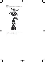
For the case of the camera with M6 screws being used:
Use the screws supplied with the bracket and a hexagonal
wrench "for M6".
(Recommended tightening torque (for common use in M5
and M6): 2.45 N·m {1.81 lbf·ft})
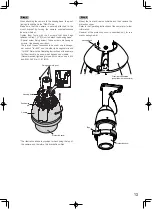
Step 4
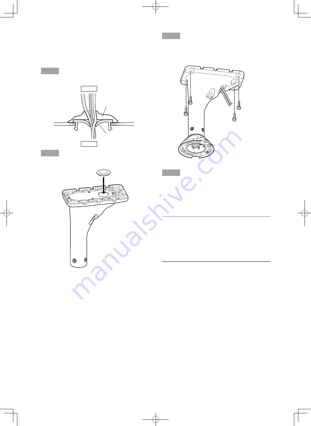
Seal the slit of the cable cap for the prevention of water
leakage.
Step 5
Mount another cable cap (accessory) on the rear plate.
* The housing base is not shown in the illustration above.
Outside
Inside
Cable
Sealant (locally procured)
Cable cap (with a slit)
Step 6
Mount the ceiling
mount bracket on the ceiling with
4 screws (M10: locally procured).
Minimum pull-out strength: 1411 N {317 lbf}/per 1 pc.
Step 7
Connect the cables to the camera outside the cable access
hole (front) of the WV-Q121B.
Connect the cables from the housing base with the cables
on the ceiling.
After cable connection, seal the connecting portion with
waterproof tape (locally procured).
IMPORTANT:
• These operations shall be performed in accordance
with the electric installation engineering standards.
Perform sealing to prevent the connecting portion of the
cables from being exposed.
Moisture may come into the camera from the gap
among the cables and cause the inside of the dome
cover to become foggy.
Go to "[3] Mounting of the camera body on the mount
bracket" (
☞
12 page).
Summary of Contents for WV-Q121BS
Page 15: ...15 ...


