11
Step 5
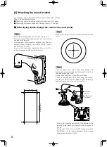
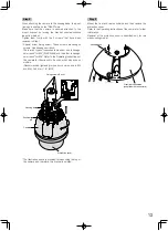
Lay the cables from the housing base via this blacket into
the slit cable cap.
Secure the housing base to the wall mount bracket.
Attach the housing base to the mount bracket using the 4
screws*.
The "REAR" mark of the housing base shall be directed to
the wire hook section.
* Refer to the Operating Instructions of the camera for the
screws and the wrenches to be used, which depends on
models.
For the case of the camera with M5 screws being used
(WV-SW598):
Use the screws supplied with the camera and a hexagonal
wrench "for M5".
For the case of the camera with M6 screws being used:
Use the screws supplied with the bracket and a hexagonal
wrench "for M6".
(Recommended tightening torque (for common use in M5
and M6): 2.45 N·m {1.81 lbf·ft})
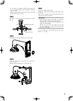
Secure the plate with the 4 screws removed in Step 4 on
the rear side of the bracket, and seal the slit of the cable
cap.
(Recommended tightening torque: 0.78 N·m {0.58 lbf·ft})
Outside
Inside
Cable
Sealant (locally procured)
Cable cap (with a slit)
Step 6
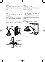
Connect the cables to the camera.
Connect the cables from the housing base with the cables
coming through the wall.
After cable connection, seal the connecting portion with
waterproof tape (locally procured).
IMPORTANT:
• These operations shall be performed in accordance
with the electric installation engineering standards.
Perform sealing to prevent the connecting portion of the
cables from being exposed.
Moisture may come into the camera from the gap
among the cables and cause the inside of the dome
cover to become foggy.
Step 7
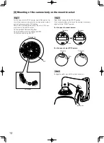
Mount this bracket on the wall with 4 screws (M10: locally
procured).
Minimum pull-out strength: 823 N {185 lbf}/per 1 pc.
Go to "[3] Mounting of the camera body on the mount
bracket" (
☞
12 page).
Summary of Contents for WV-Q122A
Page 15: ...15 ...


