background image

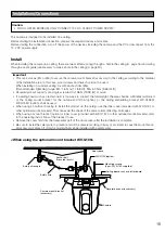
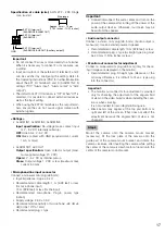
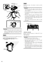
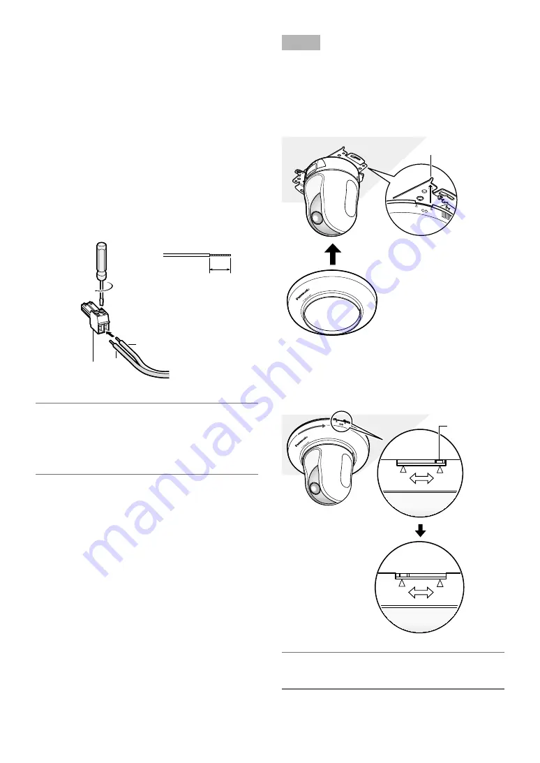
• 12 V DC power supply terminal


q

  Loosen the screw of the power cable plug (accesso-

ry).


w

  Connect the output cable to the power cable plug. 

    Strip 3 mm to 7 mm {1/8 inches to 9/32 inches} from 

the end of the wire, and twist the stripped part of the 
wire sufficiently to avoid short circuit. 

Specification of cable (wire):

 16 AWG - 24 AWG, 

Single core, twisted


*  Check whether the stripped part of the wire is not 

exposed and is securely connected.


e

  Tighten the screw of the power cable plug.


r

  Connect the power cable plug to the 12 V DC power 

supply terminal on the rear of the camera. 

  *  FOR  UL  LISTED  MODEL(S),  ONLY  CONNECT  12  V 

DC CLASS 2 POWER SUPPLY. 

Important:

  •  Be  sure  to  use  the  power  cable  plug  provided  with 

this product.

  •  Be  sure  to  fully  insert  the  power  cable  plug  into  the 

12 V  DC  power  supply  terminal.  Otherwise,  it  may 
damage the camera or cause malfunction.


Power cable plug 

(accessory)

− +

+

Approx. 3 mm - 7 mm 

{1/8 inches - 9/32 inches}

Strip range

Step 9

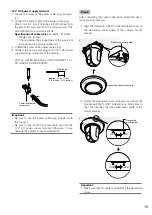
After completing the cable connections, attach the deco-
rative cover (accessory).


q

  Align the indication "OPEN" of the decorative cover to 

the  decorative  cover  guide  of  the  camera  mount 
bracket.


w

  Rotate the decorative cover clockwise into the mount 

bracket until the "LOCK" indications on both sides of 
the  cover  reaches  the  decorative  cover  guide  of  the 
mount bracket. 

Important:

  •  Make sure that no cable is pinched by the decorative 

cover.


LOCK

OPEN

WV-SC385

Decorative cover (accessory)

Decorative cover guide

LOCK

OPEN

LOCK

OPEN

LOCK

OPEN

Decorative 

cover guide

WV-SC385

19

Summary of Contents for WV-SC385PJ

Page 1: ...nstructions carefully and save this manual for future use The model number is abbreviated in some descriptions in this manual Installation Guide Network Camera Model No WV SC385PJ WV SC385 WV SC384 WV SC385E WV SC384E LOCK WV SC385 OPEN This illustration represents WV SC385 ...

Page 2: ...tinued compliance example use only shielded interface cables when connecting to com puter or peripheral devices Any changes or modifications not expressly approved by the party responsible for compli ance could void the user s authority to operate this equip ment For U S A For U S A This Class A digital apparatus complies with Canadian ICES 003 For Canada UL listed model No WV SC385 WV SC385PJ WV ...

Page 3: ...for a PC 7 Trademarks and registered trademarks 8 About copyright and license 8 Network security 8 Precautions 9 Precautions for installation 12 Major operating controls 13 Installations Connections 15 Detach the camera 25 Insert remove an SDHC SD memory card 26 Configure the network settings 28 Troubleshooting 30 Specifications 34 Standard accessories 37 Optional accessories 37 3 ...

Page 4: ...ur outlet consult an electrician for replace ment of the obsolete outlet 10 Protect the power cord from being walked on or pinched particularly at plugs convenience receptacles and the point where they exit from the apparatus 11 Only use attachments accessories specified by the manufacturer 12 Use only with the cart stand tripod bracket or table specified by the manufacturer or sold with the appar...

Page 5: ...LOW 1 ANY DAMAGE AND LOSS INCLUDING WITHOUT LIMITATION DIRECT OR INDIRECT SPECIAL CONSEQUENTIAL OR EXEMPLARY ARISING OUT OF OR RELATING TO THE PRODUCT 2 PERSONAL INJURY OR ANY DAMAGE CAUSED BY INAPPROPRIATE USE OR NEGLIGENT OPERATION OF THE USER 3 UNAUTHORIZED DISASSEMBLE REPAIR OR MODIFICATION OF THE PRODUCT BY THE USER 4 INCONVENIENCE OR ANY LOSS ARISING WHEN IMAGES ARE NOT DISPLAYED DUE TO ANY ...

Page 6: ...385 When using an optional mount bracket embedded installation on a ceiling or mounting on a wall is available Power over Ethernet function When connecting with a PoE Power over Ethernet device power will be supplied by simply connecting a LAN cable IEEE802 3af compliant Interactive communication with audio By using the audio output connector and the microphone in connector receiving audio from th...

Page 7: ...nimum of 1 GB memory is required when using Microsoft Windows 7 or Microsoft Windows Vista Network interface 10BASE T 100BASE TX 1 port Audio interface Sound card when using the audio function Monitor Image capture size 1024 x 768 pixels or more Color 24 bit True color or better OS Microsoft Windows 7 Professional 64 bit Microsoft Windows 7 Professional 32 bit Microsoft Windows Vista Business SP1 ...

Page 8: ...ncludes PCs make sure that the system is not infected by computer viruses or other malicious entities using a regularly updated anti virus program anti spyware program etc Protect your network against unauthorized access by restricting users to those who log in with an authorized user name and password Apply measures such as user authentication to protect your network against leakage or theft of i...

Page 9: ...as a fall of this product may occur The measures of protection against a fall of this product shall be taken Failure to observe this may cause a drop resulting in injury Be sure to install the safety wire The exclusively designed mount bracket shall be used Failure to observe this may cause a drop resulting in injury or accidents Use the exclusively designed mount bracket for installa tion The scr...

Page 10: ...ect access number etc About SDHC SD memory card Before inserting the SDHC SD memory card turn off the power of this product first Otherwise it may cause malfunction or damage data recorded on the SDHC SD memory card Refer to page 26 for descriptions of how to insert remove an SDHC SD memory card When using an SDHC SD memory card format it using this product Recorded data on the SDHC SD memory card...

Page 11: ...ons due to exogenous noise etc for 30 seconds or more the product will automatically reset and will return to normal state When the product is reset initialization will be carried out as when the power of the product is turned on When the product repeatedly resets exogenous noise level around the product may be high and that may cause malfunction Contact your dealer for instructions Motor operatin...

Page 12: ...re changes in temperature In case of installing the camera in such locations the dome cover may become foggy or condensation may be caused on the cover Procure fixing screws separately The screws that secure this product are not supplied Prepare them according to the material and strength of the area where the product is to be installed Screw tightening The screws and bolts must be tightened with ...

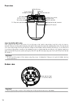
Page 13: ...ssory LOCK WV SC385 OPEN Safety wire fixed with the mount bracket Camera Decorative cover accessory Live indicator WV SC385 WV SC385 SDHC SD memory card slot SDHC SD memory card slot cover Panasonic logo plate Transparent part over the lens This illustration represents WV SC385 13 ...

Page 14: ...asing this button Wait around 3 minute after releasing the button The camera will start up and the settings including the network settings will be initialized Before initializing the settings it is recommended to write down the settings in advance The initialization will be complete when the live indicator stops blinking orange and lights off Note that the preset position settings and the CRT key ...

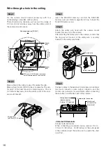
Page 15: ...he area shall be sufficiently reinforced or the ceiling mount bracket for the camera WV Q105 option or the ceiling embedding bracket WV Q155S WV Q155C option shall be used When using an outdoor housing to install the product on the ceiling use the inner cover provided with WV Q157 or other optional mount brackets That can avoid the shape of the camera from reflecting on images When using a mount b...

Page 16: ...securely hooked on the safety wire holder Step 5 Connect cables to the External I O terminals microphone line input connector audio output connector and the monitor out connector for adjustment When connecting these cables hold the base part of the camera External I O terminals Connect external devices When connecting an external device remove 9 mm 10 mm 11 32 inches 13 32 inches of the outer jack...

Page 17: ...1 V Pa 1 kHz Recommended plug L type Important Connect disconnect the audio cables and turn on the power of the camera after turning off the power of the audio output devices Otherwise loud noise may be heard from the speaker Audio output connector Connect a stereo mini plug ø3 5 mm Audio output is monaural Use an external powered speaker Recommended cable length 10 m 32 8 feet or less Recommended...

Page 18: ...h function or restart the camera to cor rect the preset positions Refer to the Operating Instructions PDF for further information Network connector Connect a LAN cable category 5 or better STP to the network connector PAL model only Important Use all 4 pairs 8 pins of the LAN cable The maximum cable length is 100 m 328 feet Make sure that the PoE device in use is compliant with IEEE802 3af standar...

Page 19: ... use the power cable plug provided with this product Be sure to fully insert the power cable plug into the 12 V DC power supply terminal Otherwise it may damage the camera or cause malfunction Power cable plug accessory Approx 3 mm 7 mm 1 8 inches 9 32 inches Strip range Step 9 After completing the cable connections attach the deco rative cover accessory q Align the indication OPEN of the decorati...

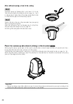
Page 20: ...he decorative cover Place the camera upside down by fixing on the bracket SC385 When using the camera upside down fix the camera using the camera mount bracket accessory to prevent a fall If nec essary attach the decorative cover accessory to the camera Install the camera by following step 1 and steps 3 9 of the Wire through a hole in the ceiling section pages 16 19 When using the camera upside do...

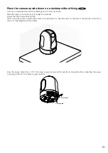
Page 21: ...the camera does not fall When using the camera upside down select On desktop for Upside down on the Cam Function tab of the setup menu Operating Instructions PDF Pass the power cable from a 12 V DC power supply accessory through the cable guides after connecting the power cable plug to the 12 V DC power supply terminal WV SC385 Cable guide Power cable MO NI T OR OU T EX T I O EX T I O 4 3 2 1 4 3 ...

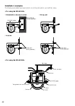
Page 22: ...angle Safety wire WV Q155S option Decorative cover Camera Inner cover Dome cover Ceiling board such as plaster board Installation examples The following are installation examples in which a mount bracket option is used with this camera For using the WV Q154S Embedded box locally procured Concrete For using the WV Q155S Strong wall 22 ...

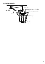
Page 23: ...y wire angle Anchor bolt Safety wire WV Q105 option Mounting screws 4 pcs WV Q105 supplied WV Q156S option Ceiling board such as plaster board Camera Inner cover Dome cover WV SC385 For using the WV Q156S 23 ...

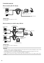
Page 24: ...cters camera title preset ID etc may not be displayed on the screen Use a switching hub or a router which is compliant with 10BASE T 100BASE TX Power supply is required for each network camera When using a PoE device hub 12 V DC power supply is unnec essary PoE device hub PC LAN cable category 5 or better straight STP Video monitor for adjustment use only Video monitor for adjustment use only LAN ...

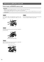
Page 25: ...ant Do not detach the camera in a different way from the one described below It may damage the camera Step 1 Rotate the decorative cover accessory counterclockwise until the indication OPEN reached the decorative cover guide of the camera mount bracket accessory Detach the decorative cover Step 2 Detach the 12 V DC power cable plug accessory and the LAN cable from the camera and then turn off the ...

Page 26: ... in the SDHC SD memory card may be damaged Step 1 Push the left corner of the Panasonic logo plate on the front panel to unlock the SDHC SD memory card slot cover Step 2 Slide the SDHC SD memory card slot cover to the left to expose the slot Step 3 Insert an SDHC SD memory card fully into the SDHC SD memory card slot until a click is heard Step 4 Shut the SDHC SD memory card slot cover and lock th...

Page 27: ... menu first Operating Instructions PDF Step 1 Open the SDHC SD memory card slot cover by following steps 1 and 2 of the How to insert an SDHC SD memory card section Step 2 Push the SDHC SD memory card until a click is heard and then pull the SDHC SD memory card from the slot Step 3 Shut the SDHC SD memory card slot cover and lock the cover by pushing the Panasonic logo plate 27 ...

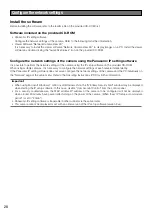
Page 28: ...ameras it is necessary to configure the network settings of each camera independently If the Panasonic IP setting software does not work configure the network settings of the camera and the PC individually on the Network page of the setup menu Refer to the Operating Instructions PDF for further information Important When using Microsoft Windows 7 or Microsoft Windows Vista the Windows Security Ale...

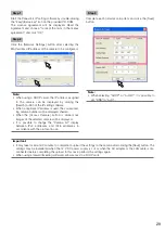
Page 29: ... be displayed shaded When the Access Camera button is clicked live images of the selected camera will be displayed It is possible to change the Camera list display between IPv4 addresses and IPv6 addresses in accordance with the protocol in use Step 3 Complete each network setup item and click the Save button Note When selecting DHCP or AutoIP it is possible to set DNS to Auto Important It may tak...

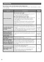
Page 30: ...refresh is set for the created schedule the camera position will be corrected periodically In some situa tions reconfigure the preset positions Operating Instructions PDF When the camera is pan ning tilting the camera stops panning tilting and mechanical noise comes from the camera The camera position may have become inaccurate Carry out the refresh position function from the Default reset tab of ...

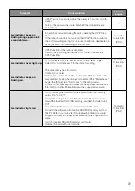
Page 31: ... Instructions PDF Live indicator keeps on blinking red The camera may be out of order Contact your dealer Refer to the readme file on the provided CD ROM for further infor mation after checking the displayed contents of the Maintenance page the Status tab Self check of the setup menu Or refer to our website http panasonic net pss security support info html for further information about the support...

Page 32: ...nd the IP address will return to the default setting 192 168 0 10 After the cam era is initialized access the camera and set the IP address again When the camera is initialized all the settings of the camera previously configured on the setup menus will be ini tialized Are the IP addresses local addresses of the different classes used for the PC and the camera The addresses local addresses of the ...

Page 33: ...en Lights green During the standby or connection Cable is not connected Lights orange During the standby or connection Cable is connected Lights green During the upgrade process Blinks orange During the initialization Blinks orange Lights off Restarts in a few minutes Port forwarding error caused by the UPnP function Blinks orange in 2 seconds intervals on for 1 second off for 1 second Trouble hap...

Page 34: ...parent part PMMA resin Camera Image sensor 1 3 type MOS image sensor Effective pixels Approx 1 3 megapixels Scanning area 4 80 mm H 3 60 mm V 3 16 inches H 5 32 inches V Scanning system Progressive Minimum illumination SC385 Color 0 5 lx 0 05 footcandle F1 6 Auto slow shutter Off 1 30 s AGC High SD Off 0 031 lx 0 0031 footcandle F1 6 Auto slow shutter max 16 30 s AGC High SD Off BW 0 06 lx 0 006 f...

Page 35: ...e range F1 6 22 Close Angular field of view Horizontal 3 2 TELE 55 2 WIDE Vertical 2 4 TELE 42 1 WIDE Panning tilting platform Panning range 0 350 Panning speed Manual Approx 0 5 s 100 s Preset Up to approx 300 s Tilting range 30 to 90 upward level downward Selectable tilting angle 10 5 3 0 3 5 10 15 20 25 30 Tilting speed Manual Approx 0 5 s 100 s Preset Up to approx 100 s Number of the preset po...

Page 36: ...NS NTP SNMP UPnP OS 3 4 Microsoft Windows 7 Professional 64 bit Microsoft Windows 7 Professional 32 bit Microsoft Windows Vista Business SP1 32 bit Microsoft Windows XP Professional SP3 Browser Windows Internet Explorer 8 0 32 bit Microsoft Windows 7 Professional 32 bit 64 bit Windows Internet Explorer 7 0 Microsoft Windows Vista Business SP1 32 bit Microsoft Internet Explorer 6 0 SP3 Microsoft Wi...

Page 37: ...WV Q155S Smoke dome type WV Q155C Clear dome type Ceiling Mount Bracket WV Q156S Smoke dome type WV Q156C Clear dome type WV Q105 Inner Cover WV Q157 User License Accessory For MPEG 4 BB HCA5A NTSC model BB HCA5CE PAL model Korea Required in Korea User License Accessory For H 264 BB HCA8A NTSC model BB HCA8CE PAL model Korea Required in Korea Important When using an inner cover WV Q157 or an acces...

Page 38: ...or more information about collection and recycling of old products and batteries please contact your local municipality your waste disposal service or the point of sale where you purchased the items Penalties may be applicable for incorrect disposal of this waste in accordance with national legislation For business users in the European Union If you wish to discard electrical and electronic equipm...

Page 39: ......

Page 40: ... New Jersey 07094 U S A Panasonic Canada Inc 5770 Ambler Drive Mississauga Ontario L4W 2T3 Canada 905 624 5010 www panasonic ca Panasonic System Networks Co Ltd 2012 NF1212 0 PGQX1275ZA Printed in Japan For Europe and other countries Panasonic Corporation http panasonic net Importer s name and address to follow EU rules Panasonic Testing Centre Panasonic Marketing Europe GmbH Winsbergring 15 22525...

Reviews: