background image

45

Example use cases

ENGLISH

To check if the distance allows for synchronization between 

antennas

To check if an area (room) can be synchronized between antennas, place the main (reference) antenna in the area that will be 
the reference for synchronization on the “Antenna location/analysis” screen, place the sub (reference) antenna in the area you 
want to check, and click the [Antenna location complete] button. Then, check the reception level with the display color of the 
antenna. If the reception level between the antennas is insufficient, change the field selection of the main (reference) antenna 
([Change TX PWR] in “How to change the settings of placed antennas” (page 33)) or change the area (room) where the main 
(reference) antenna is placed, and check the reception level between the main (reference) antenna and the sub (reference) 
antenna with the antenna’s display color.

Summary of Contents for WX-ST200P

Page 1: ...ENGLISH FRANÇAIS Operating Instructions 1 9 GHz Digital Wireless Microphone System Easy Design Tool ...
Page 2: ...9 GHz digital wireless microphone systems For information on the functions of the equipment refer to the operating instructions supplied with the products The software version information and other screen images shown in this manual are display examples and may differ from the actual screens System requirements This software can be used on a PC with the following system environment Operating syste...

Page 3: ...eviations Microsoft Windows is referred to as Windows Wireless Antenna WX SA250P is referred to as antenna Wireless Microphone WX ST200P WX ST400P WX ST700P and Gooseneck Microphone WM KG645 that is connected to Wireless Transmitter WX ST600P are referred to as microphone Personal computer is referred to as PC All information on separately sold products contained in this manual is up to date as of...

Page 4: ...n reference antenna and serves as the reference of the sub system when performing operation by wireless synchronizing between multiple antennas in a WX SR200P system Standalone antenna Antenna that is connected to a system to be operated alone or antenna that is connected to a system in which wireless synchronization with other antennas is not performed SR200 antenna Antenna other than the main re...

Page 5: ...ll 7 How to uninstall 7 Starting and exiting the software 8 How to start 8 How to exit 8 Easy wireless design operation flow 9 STEP1 Mapping 9 STEP2 Microphone location 11 STEP3 Antenna location 12 STEP4 Microphone analysis 13 Mapping 14 Loading a map when map available 14 Loading a map when map not available 16 Loading a map loading a saved file 17 Area input 18 Adding input areas 19 Changing and...

Page 6: ...placed antennas 33 Complete antenna location 35 Checking synchronization between antennas 37 Microphone analysis 39 Installation analysis 39 Output 41 Print 41 Saving files 43 Save 43 Save as 43 Example use cases 44 Checking synchronization 44 If the synchronized antennas are displayed in orange or red 44 To check if the distance allows for synchronization between antennas 45 Troubleshooting 46 ...

Page 7: ... software following the instructions on the screen When installation is complete this software is registered in the Start menu memo Important A shortcut for this software is created in Start Panasonic WX SR200P Series Easy Design Tool How to uninstall To uninstall this software perform the following procedure The uninstallation procedure is described based on operation in Windows 10 Please substit...

Page 8: ...elect Start Panasonic WX SR200P Series Easy Design Tool to start this software This software starts and the following screen appears How to exit Exit this software by selecting File Exit This software can also be exited from the X mark at the top right ...

Page 9: ...s described in the messages displayed on the screens of this software STEP1 Mapping Select File Create new Load map file and then load the map of the planned installation location If there is no map select No map a blank page area input screen will appear Easy wireless design operation flow ...

Page 10: ... system Select WX SR200P from the area input tool 2 Input the areas Click the opposite angles of a room according to the map Repeat the above step for just the number of areas to be input 3 Set the scale Adjust the length of the scale arrowed line to match the dimension 4 Complete the area input When area input is complete click the Area input complete button memo Important For details on loading ...

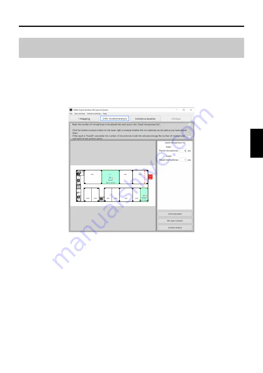
Page 11: ...in each area When inputting the number of microphones is complete click the Location analysis button 2 1 Microphone location procedure 1 Input the number of microphones Input the number of microphones to be used in each area in the Used microphone list 2 Click the Mic input complete button When microphone input is complete click the Mic input complete button memo Important For details on microphon...

Page 12: ...ct an antenna from the Antenna selection tool and then click in the area in which to add it The antenna is added in the area 3 Delete antennas Select an antenna to delete right click to display a menu and select Delete 4 Complete antenna location Click the Antenna location complete button Click the Antenna location complete button to check which area each area is synchronized with and the synchron...

Page 13: ... again and check the number of microphones that can be used 2 Select the 4 Output tab The screen switches to the Output screen The models and quantities required for the installed wireless system are displayed and you can create the estimate price and print the result memo Important For details on microphone location and analysis refer to Microphone analysis page 39 For details on the Output scree...

Page 14: ...as rooms Loading a map when map available This software allows you to load a floor plan map for considering wireless microphone system installation Map file load procedure 1 Load the map Select File Create new Load map file and then select the map of the planned installation location The map is displayed on the screen Mapping ...

Page 15: ... loaded a blank screen will be displayed after loading In such a case create a map file with the following procedure Map file creation procedure A Open the PDF file in Acrobat Reader B Take a snapshot image of the map to be loaded with the selection tool C Select Start All Programs Accessories Paint in Microsoft Windows to start Paint D Paste the snapshot captured in Acrobat Reader into Paint E Sa...

Page 16: ... is no map to load into this software select No map The screen after selecting No map will be the blank page map screen shown below Procedure to start without a existing map 1 Select No map Select File Create new No map A blank map is displayed on the screen ...

Page 17: ...g ENGLISH Loading a map loading a saved file This software can save analysis results and load a saved file Saved file load procedure 1 Load a saved file Select File Load saved file and then select the saved file ...

Page 18: ...system Click the WX SR200P button of the area input tool 2 Set the areas To determine the area to be input click one of the four corners and then click the corner diagonally opposite A light purple rectangular appears and its area is input Input the areas of all rooms in which the WX SR200P system is to be installed memo Important The input areas can be moved and resized by dragging with the mouse...

Page 19: ...he procedure in Area input page 18 to set areas rooms where the wireless microphone system will be placed Enlarging the map You can enlarge the map or revert it to the original size by holding down the Ctrl key and scrolling the mouse on the map The following is an example of an enlarged map ...

Page 20: ...nes is all of the area room or part of the area Normally set this to All All Uses microphones in all of the area Upper side Uses microphones in the upper side of the area Lower side Uses microphones in the lower side of the area Right side Uses microphones in right side of the area Left side Uses microphones in the left side of the area Default setting All For example in the case of a classroom wh...

Page 21: ...or each area If we use the figure below as an example when the insertion loss between area 1 and area 2 is known to be 10 dB set 5 dB for the insertion loss of the lower side of area 1 and also set 5 dB for the insertion loss of the upper side of area 2 The following table shows examples of the transmission losses of building materials Material thickness 1900 MHz Partition material Wood panel 15 m...

Page 22: ...Mapping 22 X Delete Delete an area memo Important You can also change the input area settings from Area settings in the menu ...

Page 23: ...lways set it Scale setting procedure 1 Click the scale arrowed line 2 Adjust the angle length and position of the scale arrowed line Adjust the length and position of the scale arrowed line to match the size of the area If you right click the arrowed line you can change the angle of the arrowed line For example if the dimension is shown on the loaded map adjust the length of the scale arrowed line...

Page 24: ... Set scale window appears Input a numerical value memo Important To return to the original 0 or 90 after changing the angle of the scale right click the scale and select 0 or 90 from the menu After clicking to select you can also change the scale setting from Area settings in the menu ...

Page 25: ...itches to the Mic location analysis screen memo Important If you move or change an area while working on another tab Mic location analysis Antenna location analysis etc the work tab switches to Mapping If you have moved resized or changed the settings of an area click the Area input complete button to apply the changes ...

Page 26: ...n analysis screen In the Mic location analysis screen place the microphones in each area room Used microphone input 1 Input the number of microphones In the Used microphone list on the right side of the screen input the number of microphones you plan to place in each area Microphone list ...

Page 27: ...ophone location ENGLISH 2 Complete the microphone input When inputting the number of microphones for each area is complete click the Mic input complete button The screen switches to the Antenna location screen ...

Page 28: ...commended antenna location This software proposes the recommended location for the wireless microphone system Recommended location procedure 1 Execute recommended antenna location Click the Recommended antenna location button The antennas are placed in the recommended positions in each area ...

Page 29: ...29 Antenna location ENGLISH In recommended location a main reference antenna and sub reference antennas are placed when the number of microphones used in an area is 9 or more ...

Page 30: ...umber of microphones system configuration and antenna location example Number of microphones System configuration Antenna location example Up to 2 microphones SR202P x1 From 3 to 4 microphones SR204P x1 From 5 to 6 microphones SR202P x1 SR204P x1 From 7 to 8 microphones SR204P x1 SE200P x1 From 9 to 10 microphones SR202P x1 SR204P x1 SE200P x1 From 11 to 12 microphones SR204P x2 SE200P x1 From 13 ...

Page 31: ...s dotted circles You can display and hide them by pressing the Switch coverage area display button after placing antennas memo Important The displayed circle is an estimate so calls are not necessarily guaranteed inside the circle If the dotted circle is green the reach is displayed as an estimate while taking the wall thickness into account ...

Page 32: ...ccording to the design plan Adding antennas To add an antenna select the antenna to add in the Antenna selection tool and click in the area in which to add it An antenna of a system different to that of the area cannot be added Antenna selection tool Moving placed antennas To change the position of a placed antenna move the antenna by dragging it ...

Page 33: ...enna in a WX SR200P system SR200 Sub reference antenna Use the antenna as a sub reference antenna in a WX SR200P system SR200 Main reference antenna Use the antenna as the main reference antenna in a WX SR200P system SR200 Standalone Use the antenna as a standalone antenna in a WX SR200P system X Change TX PWR Set the field selection of each antenna When the antenna type is set to SR200 Antenna SR...

Page 34: ...on floor directly above If you select Reference antenna on floor directly below above the antenna placement analysis is made by calculating the influence from the reference antenna s from above and or below floor s For example if there is a reference antenna of a WX SR200P system with a large field selection installed on the floor above set Reference antenna on floor directly above Furthermore als...

Page 35: ...s indicated by a red frame as shown in the figure below Cause of error An error occurs because the antenna coverage area does is not large enough to cover the size of the area room For example if the setting of Mic usage side page 20 for an area is All an error will occur if the antenna coverage area does not extend to the four corners of the area room In the case of the figure above an error occu...

Page 36: ... shift in the antenna location will result in an error The reason for this is that the antenna coverage area is equal to the area size so it is not possible to cover the four corners of the area with slight shifting In such a case do not change the antenna location from the recommended antenna location and instead change the antenna settings How to change the settings of placed antennas page 33 Fo...

Page 37: ...h from the main reference antenna is also displayed as the color of the antenna The display settings are as follows Green Displayed in green if it is sufficiently within the coverage area of the main reference antenna Try to synchronize the antennas within this display color range Orange Displayed in orange if the location is far from the main reference antenna For this display color increase the ...

Page 38: ...ement of synchronization between antennas needs to be revised an example when the insertion loss between areas is relatively large The location of the sub reference antennas in Area1 and Area3 should be revised as well as the field selection of the main antenna in Area2 ...

Page 39: ... analysis 1 Execute installation analysis Check the number of microphones in each area If you need to change the number of microphones change it However after changing the number of microphones execute Mic input complete and Antenna location complete again After checking the number of microphones click the Location analysis button ...

Page 40: ... number of microphones cannot be used because for example there are insufficient wireless resources Result NG is displayed and the number of antennas of any NG area turns red Revise the number of microphones in the NG area and the areas surrounding it If the result is displayed as NG Too many microphones you must revise the number of microphones to be installed in the target area ...

Page 41: ...mate Print 1 Click the Print button The estimate is printed 2 Print the analysis results A dialog box to confirm whether or not to also print the analysis results appears Print the analysis results if necessary memo Important A change cannot be made to a number of devices that is definitely required to construct the system If you select the Select Dante model checkbox the receiver and additional r...

Page 42: ...s Handheld wireless microphone WX ST200P 18 pcs Wireless body pack microphone WX ST400P 0 pcs Wireless transmitter mic included WX ST600 KG645 0 pcs Boundary wireless microphone WX ST700 0 pcs Charger WX SZ600 6 pcs Charger WX SZ200P 0 pcs Total estimated cost 21648 00 1 9GHz Digital Wireless Microphone System Estimate Total microphones in use 18pcs Wireless receiver 2ch WX SR202P 3 pcs Wireless r...

Page 43: ... you wish In addition you can share files between PCs with this software installed Save When you wish to save your work after opening a file saved with this software and then carrying out more work use the save function Select File Save Save as When you wish to save your work after beginning new work in this software use the save as function Select File Save As Specify the save location and name o...

Page 44: ...n orange or red even with the recommended antenna location In that case change the antenna settings individually so that multiple main reference antennas are placed If there are multiple main reference antennas the synchronization area displayed in each area after clicking the Antenna location complete button in the Antenna location analysis screen displays the area where the main reference antenn...

Page 45: ...n the area you want to check and click the Antenna location complete button Then check the reception level with the display color of the antenna If the reception level between the antennas is insufficient change the field selection of the main reference antenna Change TX PWR in How to change the settings of placed antennas page 33 or change the area room where the main reference antenna is placed ...

Page 46: ...easures or a symptom not listed in this table occurs contact your retailer for more information Symptom Cause measure Reference page Saved file cannot be loaded The file may be corrupted or you may not be using the latest version of the Easy Design Tool Ask a retailer to obtain the Easy Design Tool 17 Troubleshooting ...

Page 47: ...es sans fil numérique 1 9 GHz Pour en savoir plus sur les fonctions de l équipement consultez les instructions de fonctionnement fournies avec les produits Les informations de version du logiciel et autres images d écran indiquées dans ce manuel sont des exemples d affichage et peuvent différer des écrans réels Exigences du système Vous pouvez utiliser ce logiciel sur un PC avec l environnement sy...

Page 48: ...signe l antenne sans fil WX SA250P Le terme microphone désigne le microphone sans fil WX ST200P WX ST400P WX ST700P et le microphone col de cygne WM KG645 connectés au transmetteur sans fil WX ST600P Le PC désigne l ordinateur personnel Tous les renseignements sur les produits vendus séparément contenus dans ce manuel sont des mises à jour d octobre 2022 Communiquez avec un détaillant pour obtenir...

Page 49: ... principale et sert de référence pour le système auxiliaire lors du fonctionnement par l intermédiaire de la synchronisation sans fil entre plusieurs antennes dans un système WX SR200P Antenne autonome Antenne connectée à un système pouvant fonctionner seule ou connectée à un système dans lequel la synchronisation sans fil avec d autres antennes n est pas réalisée Antenne SR200 Antenne différente ...

Page 50: ...ciel 53 Démarrage 53 Sortie 53 Procédure de fonctionnement sans fil simplifiée 54 ÉTAPE1 cartographie 54 ÉTAPE2 emplacement des microphones 56 ÉTAPE3 emplacement des antennes 57 ÉTAPE4 analyse des microphones 58 Cartographie 59 Chargement d une carte si disponible 59 Chargement d une carte si la carte n est pas disponible 61 Chargement d une carte à partir d un fichier enregistré 62 Saisie des emp...

Page 51: ...cées 78 Finissez l emplacement des antennes 80 Vérification de la synchronisation entre les antennes 82 Analyse des microphones 84 Analyse de l installation 84 Sortie 86 Imprimer 86 Enregistrement des fichiers 88 Enregistrer 88 Enregistrer sous 88 Exemples de cas d utilisation 89 Vérification de la synchronisation 89 Si les antennes synchronisées sont affichées en orange ou en rouge 89 Pour vérifi...

Page 52: ...z le logiciel conformément aux instructions à l écran Lorsque l installation est terminée ce logiciel est enregistré dans le menu Démarrer note Important Un raccourci vers ce logiciel est créé dans Start Panasonic WX SR200P Series Easy Design Tool Procédure de désinstallation Pour désinstaller ce logiciel suivez la procédure suivante La procédure de désinstallation est décrite d après le fonctionn...

Page 53: ...P Series Easy Design Tool pour démarrer ce logiciel Ce logiciel démarre et les instructions suivantes apparaissent à l écran Sortie Quittez ce logiciel en sélectionnant File Exit Il est également possible de quitter ce logiciel en cliquant sur la croix X située dans le coin supérieur droit ...

Page 54: ...rit dans les messages affichés à l écran dans le logiciel ÉTAPE1 cartographie Sélectionnez File Create new Load map file puis chargez la carte de l emplacement d installation prévu En l absence de carte sélectionnez No map un écran de saisie sur une page vide apparaîtra Procédure de fonctionnement sans fil simplifiée ...

Page 55: ...util de saisie des emplacements 2 Saisissez les emplacements Cliquez sur les angles opposés d une pièce en fonction de la carte Répétez l étape ci dessus pour chacun des emplacements à saisir 3 Définissez l échelle Ajustez la longueur de la ligne fléchée de l échelle pour la faire correspondre à la dimension 4 Finissez de saisir les emplacements Lorsque la saisie des emplacements est terminée cliq...

Page 56: ... microphones est terminée cliquez sur le bouton Location analysis 2 1 Procédure d emplacement des microphones 1 Saisissez le nombre de microphones Saisissez le nombre de microphones à utiliser à chaque emplacement dans Used microphone list 2 Cliquez sur le bouton Mic input complete Lorsque la saisie des microphones est terminée cliquez sur le bouton Mic input complete note Important Pour obtenir p...

Page 57: ...uez sur l emplacement dans lequel vous souhaitez l ajouter L antenne est ajoutée à l emplacement indiqué 3 Supprimez des antennes Sélectionnez une antenne à supprimer faites clic droit pour afficher un menu et sélectionnez Delete 4 Finissez l emplacement des antennes Cliquez sur le bouton Antenna location complete Appuyez sur le bouton Antenna location complete pour connaitre quelle zone est synch...

Page 58: ...z le nombre de microphones pouvant être utilisés 2 Sélectionnez l onglet 4 Output L écran Output apparaît Les modèles et quantités nécessaires pour le système sans fil installé s affichent et vous pouvez créer un devis prix et imprimer le résultat note Important Pour obtenir plus d informations concernant l emplacement des microphones et l analyse consultez Analyse des microphones page 84 Pour obt...

Page 59: ...argement d une carte si disponible Ce logiciel vous permet de charger un plan de l étage carte pour préparer l installation d un système de microphones sans fil Procédure de chargement du fichier de carte 1 Chargez la carte Sélectionnez File Create new Load map file puis sélectionnez la carte de l emplacement d installation prévu La carte s affiche à l écran Cartographie ...

Page 60: ...chargement Dans ce cas créez un fichier de carte en suivant la procédure suivante Procédure de création du fichier de carte A Ouvrez le fichier PDF dans Acrobat Reader B Capturez une image instantanée de la carte à charger à l aide de l outil de sélection C Sélectionnez Start All Programs Accessories Paint dans Microsoft Windows pour démarrer Paint D Copiez l instantané capturé par l intermédiaire...

Page 61: ...ne carte ne peut être chargée dans ce logiciel sélectionnez No map Une fois que vous avez sélectionné No map l écran blanc de carte ci dessous s affiche Procédure de démarrage sans carte existante 1 Sélectionnez No map Sélectionnez File Create new No map Une carte vide s affiche à l écran ...

Page 62: ...ichier enregistré Ce logiciel peut enregistrer les résultats de l analyse et charger un fichier enregistré Procédure de chargement du fichier enregistré 1 Chargez un fichier enregistré Sélectionnez File Load saved file et sélectionnez le fichier enregistré ...

Page 63: ... sur le bouton WX SR200P de l outil de saisie des emplacements 2 Définissez les emplacements Pour déterminer l emplacement à saisir cliquez sur l un des quatre coins puis cliquez sur le coin diagonalement opposé Un rectangle violet clair apparaît et son emplacement est saisi Saisissez les emplacements de toutes les pièces dans lesquelles le système WX SR200P doit être installé note Important Les e...

Page 64: ...dans Saisie des emplacements page 63 pour définir les zones pièces où le système de microphone sans fil sera placé Agrandissement de la carte Vous pouvez agrandir la carte ou la ramener à sa taille originale en maintenant la touche Ctrl enfoncée et en défilant la souris sur la carte Ce qui suit est un exemple d une carte agrandie ...

Page 65: ...ut l emplacement pièce ou seulement une partie de l emplacement Par défaut définissez ce paramètre sur All All utilisation des microphones dans tout l emplacement Upper side utilisation des microphones dans la zone supérieure de l emplacement Lower side utilisation des microphones dans la zone inférieure de l emplacement Right side utilisation des microphones dans la zone droite de l emplacement L...

Page 66: ... insertion pour le mur de chaque emplacement En utilisant la figure ci dessous comme exemple lorsque la perte d insertion entre l emplacement 1 et l emplacement 2 est connue et équivaut à 10 dB définissez la perte d insertion de la zone inférieure de l emplacement 1 sur 5 dB et la perte d insertion de la zone supérieure de l emplacement 2 sur 5 dB Le tableau suivant montre des exemples de pertes d...

Page 67: ...67 Cartographie FRANÇAIS X Delete Supprimez un emplacement note Important Vous pouvez également modifier les paramètres de l emplacement saisi à partir de Area settings dans le menu ...

Page 68: ...cédure de définition de l échelle 1 Cliquez sur la ligne fléchée de l échelle 2 Ajustez l angle la longueur et la position de la ligne fléchée de l échelle Ajustez la longueur et la position de la ligne fléchée de l échelle pour la faire correspondre à la taille de l emplacement Faites clic droit sur la ligne fléchée pour modifier son angle Par exemple si la dimension est affichée sur la carte cha...

Page 69: ...z une valeur numérique note Important Pour rétablir la valeur initiale de 0 ou 90 après avoir modifié l angle de l échelle faites clic droit sur l échelle et sélectionnez 0 ou 90 à partir du menu Une fois que vous avez cliqué sur l échelle pour la sélectionner vous pouvez également modifier les paramètres de l échelle à partir de Area settings dans le menu ...

Page 70: ... apparaît alors note Important Si vous déplacez ou modifiez un emplacement tout en travaillant sur un autre onglet Mic location analysis Antenna location analysis etc l onglet sur lequel vous travaillez passe à Mapping Si vous avez déplacé redimensionné ou modifié les paramètres d un emplacement cliquez sur le bouton Area input complete pour appliquer les modifications ...

Page 71: ...fiche Dans l écran Mic location analysis placez les microphones dans chaque emplacement pièce Saisie des microphones utilisés 1 Saisissez le nombre de microphones Dans Used microphone list sur la droite de l écran saisissez le nombre de microphones que vous prévoyez d installer dans chaque emplacement Liste des microphones ...

Page 72: ...es microphones 72 2 Finissez de saisir les microphones Lorsque la saisie du nombre de microphones est terminée pour chaque emplacement cliquez sur le bouton Mic input complete L écran Antenna location apparaît alors ...

Page 73: ...emplacement des antennes Ce logiciel propose des recommandations d emplacement pour le système de microphones sans fil Procédure d emplacement recommandé 1 Réalisez l emplacement des antennes recommandé Cliquez sur le bouton Recommended antenna location Les antennes sont placées dans les positions recommandées dans chaque emplacement ...

Page 74: ...acement des antennes 74 Dans les emplacements recommandés une antenne de référence principale et des antennes de référence auxiliaires sont placées lorsque le nombre de microphones est supérieur ou égal à 9 ...

Page 75: ...uxiliaires consultez les Instructions d utilisation de WX SR202P 204P Exemple du nombre de microphones de configuration du système et d emplacement des antennes Nombre de microphones Configuration du système Exemple d emplacement des antennes Jusqu à 2 microphones SR202P x1 De 3 à 4 microphones SR204P x1 De 5 à 6 microphones SR202P x1 SR204P x1 De 7 à 8 microphones SR204P x1 SE200P x1 De 9 à 10 mi...

Page 76: ...es pointillés sur la carte Vous pouvez les afficher ou les cacher en appuyant sur le bouton Switch coverage area display après avoir placé les antennes memo Important Le cercle affiché est une estimation les appels ne sont donc pas garantis à l intérieur du cercle Si le cercle pointillé est vert la portée est présentée en tant qu une estimation en tenant compte de l épaisseur du mur ...

Page 77: ...nception Ajout d antennes Pour ajouter une antenne sélectionnez l antenne à ajouter dans Antenna selection tool et cliquez sur l emplacement dans lequel vous souhaitez l ajouter Une antenne d un système différent de celui de l emplacement ne peut pas être ajoutée Outil de sélection des antennes Déplacement d antennes placées Pour modifier la position d une antenne placée déplacez l antenne en fais...

Page 78: ... de l antenne de référence auxiliaire dans un système WX SR200P SR200 Sub reference antenna utilisez l antenne en tant qu antenne de référence auxiliaire dans un système WX SR200P SR200 Main reference antenna utilisez l antenne en tant qu antenne de référence principale dans un système WX SR200P SR200 Standalone utilisez l antenne auxiliaire en tant qu antenne autonome dans le système WX SR200P X ...

Page 79: ...tenna on floor directly above Si vous sélectionnez Reference antenna on floor directly below above l analyse du placement de l antenne est réalisée en calculant l influence de toute antenne de référence du ou des étages au dessus en dessous Par exemple si une antenne de référence d un système WX SR200P est présente avec un champ large et qu elle est installée à l étage au dessus choisissez l optio...

Page 80: ...la figure ci dessous Cause de l erreur Une erreur survient lorsque le champ couvert par l antenne n est pas suffisamment grand pour couvrir la totalité de l emplacement pièce Par exemple si le paramètre de Mic usage side page 65 pour un emplacement est défini sur All une erreur surviendra si le champ couvert par l antenne ne s étend pas jusqu aux quatre coins de l emplacement pièce Dans le cas ill...

Page 81: ...me un léger décalage dans l emplacement de l antenne entraînera une erreur La raison étant que la surface de couverture de l antenne est égale à la taille de la zone il n est donc pas possible de couvrir les quatre coins avec une légère déviation Dans un tel cas ne modifiez pas l emplacement recommandé de l antenne mais modifiez plutôt les réglages de l antenne consultez Procédure de changement de...

Page 82: ...férence est également affichée au couleur de l antenne Les paramètres de l affichage sont comme suit Vert Affiché en vert s il est suffisamment à l intérieur de la zone couverte par l antenne principale référence Essayez de synchroniser les antennes dans cette gamme de couleur d affichage Orange Affiché en orange si l emplacement est loin de l antenne principale référence Pour cette couleur d affi...

Page 83: ... la synchronisation entre les antennes doit être révisé un exemple lorsque la perte d insertion entre les zones est relativement importante L emplacement des antennes sous références dans les Area1 et Area3 doit être révisé ainsi que le champ de sélection de l antenne principale dans la Area2 ...

Page 84: ...z une analyse de l installation Vérifiez le nombre de microphones dans chaque zone Si vous devez modifier le nombre de microphones faites le Toutefois après avoir modifié le nombre de microphones effectuez de nouveau Mic input complete et Antenna location complete Après la vérification du nombre de microphones appuyez sur le bouton Location analysis ...

Page 85: ...iser le nombre de microphones prévus par exemple en raison de ressources sans fil insuffisantes Result NG s affiche et le numéro des antennes de tout emplacement non valide devient rouge Modifiez le nombre de microphones dans l emplacement non valide et dans les emplacements qui l entourent Si le résultat s affiche comme NG trop de microphones vous devez réviser le nombre de microphones à installe...

Page 86: ...rint Le devis est imprimé 2 Imprimez les résultats de l analyse Une boîte de dialogue destinée à indiquer si vous voulez ou non imprimer également les résultats de l analyse apparaît Imprimez les résultats de l analyse si nécessaire note Important Il est impossible d apporter des modifications à un nombre d appareils absolument nécessaire à la construction du système Si vous cochez la case Select ...

Page 87: ... WX SA250P 5 pcs Handheld wireless microphone WX ST200P 18 pcs Wireless body pack microphone WX ST400P 0 pcs Wireless transmitter mic included WX ST600 KG645 0 pcs Boundary wireless microphone WX ST700 0 pcs Charger WX SZ600 6 pcs Charger WX SZ200P 0 pcs Total estimated cost 21648 00 1 9GHz Digital Wireless Microphone System Estimate Total microphones in use 18pcs Wireless receiver 2ch WX SR202P 3...

Page 88: ...artager des fichiers entre PC à condition que ce logiciel y soit aussi installé Enregistrer Lorsque vous voulez enregistrer votre travail après avoir ouvert un fichier enregistré avec ce logiciel et que vous voulez effectuer des tâches supplémentaires utilisez la fonction d enregistrement Sélectionnez File Save Enregistrer sous Lorsque vous souhaitez enregistrer votre travail après avoir commencé ...

Page 89: ...ffichées en orange ou en rouge même avec l emplacement recommandé d antenne Dans une telle éventualité modifiez individuellement les paramètres de l antenne de manière à placer plusieurs antennes principales référence Dans le cas de plusieurs antennes principales référence la zone de synchronisation affichée dans chaque zone après avoir appuyé sur le bouton Antenna location complete dans l écran A...

Page 90: ...z vérifier puis appuyez sur le bouton Antenna location complete Vérifiez par la suite le niveau de réception avec la couleur de l affichage de l antenne Si le niveau de réception entre les antennes est insuffisant modifiez la sélection de champ de l antenne principale référence Change TX PWR dans Procédure de changement des paramètres des antennes placées page 78 ou modifiez la zone pièce où l ant...

Page 91: ...e le problème ou si un symptôme ne figure pas dans ce tableau contactez votre détaillant pour plus d informations Symptôme Cause mesure Page de référence Le fichier enregistré ne peut pas être chargé Le fichier peut être corrompu ou vous ne disposez pas de la plus récente version de Easy Design Tool Demandez à un détaillant pour obtenir Easy Design Tool 62 ...

Page 92: ...oration of North America Two Riverfront Plaza Newark NJ 07102 5490 https na panasonic com us Panasonic Canada Inc 5770 Ambler Drive Mississauga Ontario L4W 2T3 Canada 1 877 495 0580 https www panasonic com ca Panasonic Connect Co Ltd 2022 ...

Reviews: