


Panasonic Corporation
Automation Controls Business Unit
industrial.panasonic.com/ac/e
AYF51
ACCTB19E 201201-T
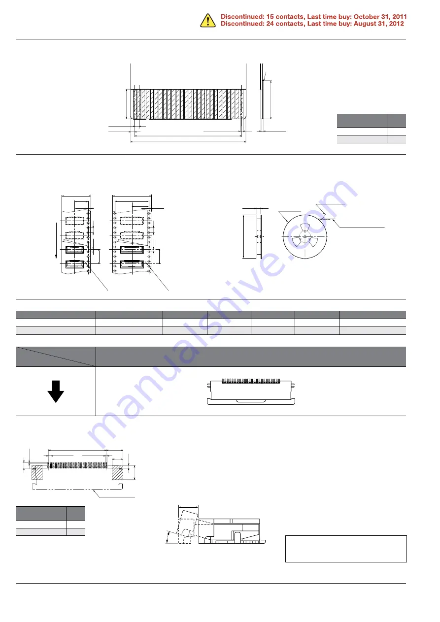
RECOMMENDED FPC/FFC DIMENSIONS
EMBOSSED TAPE DIMENSIONS
(Unit: mm)
• Dimension table
(Unit: mm)
• Connector orientation with respect to embossed tape feeding direction
NOTES
Number of pins
Type of taping
A
B
C
D
Quantity per reel
15 pin contacts
Tape I
24.0
–
11.5
25.0
2,000
24 pin contacts
Tape II
32.0
28.4
14.2
33.0
2,000
Reinforcing plate
0.30
±
0.05
(4.00)
3.00min.
(FFC)
(FPC)
0.30
0.35
±
0.03
+0.05
–0.02
B
±
0.05
0.50
±
0.05
0.50
±
0.10
(B+1)
±
0.07
Surface finish: Au plating
Number of pins/
dimension
B
15
7.0
24
11.5
• Specifications for taping
• Specifications for reel
Tape I
Tape II
(A
±
0.30)
(B)
(C)
(1.75)
(4.0)
(2.0)
12.0
1.55+0.05 dia.
Leading direction after pac
kaging
(A
±
0.30)
(C)
(1.75)
(4.0)
(2.0)
12.0
1.55+0.05 dia.
Taping reel
Top cover tape
Embossed carrier tape
370 dia.
(D
±
1)
Type
Direction
of tape progress
Y5S
1. Recommended PC board pattern
2. Precautions for insertion/removal of
FPC/FFC
A load applied to the slider unevenly or
on only one side may deform the slider.
Fully open the slider lock to insert an
FPC. Don’t further apply an excessive
load to the fully released slider lock;
otherwise, the slider may be deformed.
Remove the FPC in a direction parallel to
the board with the slider lock fully
released. If the slider is closed, or if the
FPC is forcedly pulled into a direction
parallel to the board, the connector may
break.
After an FPC is inserted, carefully handle
it so as not to apply excessive stress to
the base of the FPC.
Number of pins/
dimension
B
15
7.0
24
11.5
Connector outline
0.50
±
0.05
3.30
2.10
B
±
0.05
1.10
(0.20)
2.80
0.50
0.30
±
0.05
(1.55)
(15
°
)
Please refer to the latest product
specifications when designing your
product.


