3DQDVRQLF
26
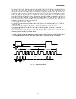
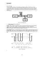
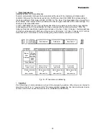
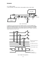
Functioning and waveform explanation
1.3.2.1.1
From t
1
to t
2
:
At the initial moment t
1
, the electron beam is aimed at the center of a line since the deflection current
is zero (iy=0) and there is no horizontal deflection magnetic field. The capacitor Cs is charged and will
be discharged between t
1
and t
2
. As the transistor Tr is in a conductive state, Ct remains discharged
(Vct=0) between t
1
and t
2
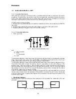
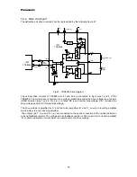
. The circuit in figure 17 can be simplified (see figure 20). Then we can
evaluate the horizontal deflection current i
y
.
V
CC
V
Cs
V
Ly
L
1
T
r
Current flow
Fig. 20 : Between t
1
and t
2
We can write V
cs
= V
Ly
We can write V
Cs
= V
Ly
with
VV
C
i dx
Cs
S
y
t
t
= −
∫
1
1
VV
L
di
dt
Ly
y
y
=
Then
1
0
1
Cs
i dx
Ly
di
dt
y
t
t
y
∫
+
=
⇒ +
=
i
LyCs
d i
dt
y
y
2
2
0
The solution for this equation is :
i
y
= I
0
sin
ω
t
with
ω
=
1
LyCs
The iy oscillating period ( F= 2
π√
LyCs ) is much higher than the time t2-t1. Then the shape of current
iy is almost a straight line ( with a S-Correction shape)
•
From t
2
to t
3
and t
4
(retrace time)
At t
2
, the transistor stops conducting. All the current circulating through the transistor is out off. Then
Ct is charging between t
2
and t
3
, reaching its maximum voltage at the instant t
3
, and discharging
between t
3
and t
4
. Cs continues to discharge until t
3
and then starts to charge again. The circuit in fig
17 can be represented by simplified diagram shows on figure 21 arid figure 22.


