3DQDVRQLF
47
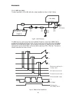
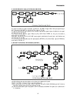
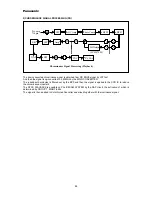
(3) The output AUDIO signal at the 1st pin through REC AMP is recorded on HEAD after being mixed with
the 70KHz AC BIAS signal.
At the same time, the output AUDIO signal is supplied to the 3rd pin and then filtered by 60KHz HPF, so
only the 70KHz AC BIAS signal is passed.
The pure 70KHz AC BIAS signal is then compared to the voltage of 440mV at the comparator, so the AC
BIAS signal is controlled to maintain at 440mV.
(4) The recording current is determined by the 440mVrms BIAS signal and the resistance between the 1st
and the 3rd pin.
* The method to set the recording current.
BIAS=440mVrms ÷ the resistance between the 1st and the 3rd pin.
ex) 440mVrms ÷ 1.3K OHM = 338µA
where, only the low error, G type resistor should be used here.
As a rule of thumb, the resistance between the 1st and the 3rd pin should range from 1.0 ohm to 2.2K ohm.
5) The conventional AUDIO circuitry uses a peaking COIL to enhance the high frequency region, but the
LA71511M uses the resistance of R/P HEAD.
Accordingly, The resistor and the capacitor is used to fit the frequency characteristics.
4. BIAS COIL
For normal operation of AUTO BIAS, the oscillating voltage of R/P HEAD is over 40Vp-p, A/E HEAD is over
20Vp-p, and the FE HEAD is over 40Vp-p.
Especially, the erasing current of F/E HEAD ranges from 130 to 280mA, and it should be 180mA when the
HEAD impedance is at the center.


