OMAP
TM
4 PandaBoard System
Reference Manual
Revision 0.4
September 22, 2010
DOC-21010
Page 14 of 83
2
OMAP4430 PandaBoard Architecture
This chapter explains the architecture of the OMAP4430 PandaBoard.
2.1
Overview of the PandaBoard Architecture
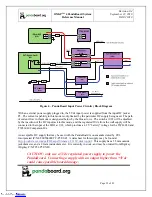
Shown in Figure 1 is the Architectural Block Diagram of the OMAP4430 PandaBoard.
Listed below are the major components used on the PandaBoard.
à
OMAP4430 Processor
à
TWL6030 (Phoenix) Power Management Companion Device
à
TWL6040 (Phoenix) Audio Companion Device
à
POP Mobile LPDDR2 SDRAM Memory
à
HDMI Connector (Type A) – for OMAP4430 HDMI Transmitter output
à
HDMI Connector (Type A) – for DVI-D output sourced via OMAP4 parallel display output
à
Audio Input & Output Connectors (3.5mm)
à
SD/SDIO/MMC Media Card Cage
à
UART via RS-232 interface via 9-pin D-Sub Connector
à
LS Research Module – 802.11b/g/n, Bluetooth, FM
The Platform also includes connectors that can be used for additional functionality and/or expansion
purposes. These connectors are not populated on the platform, but can be installed by the user. They are
indicated by the blue blocks in Figure 1, and include:
à
Camera Connector (J17)
à
LCD Expansion Connectors (J1 and J4)
à
Generic Expansion Connectors (J3 and J6)
à
Composite Video Header (J12)
See Figure 2 on page 16 for a top side view of the Panda Platform.
The core components of the PandaBoard will be discussed in this section of the document. This would
include the OMAP4430 Processor and its POP LPDDR2 memory, the input clock circuitry, the TWL6030
Power Companion IC, and the TWL6040 Audio Companion IC. The functional interfaces will be
discussed in later sections of the document.
Downloaded from
Downloaded from
Downloaded from
Downloaded from
Downloaded from
Downloaded from
Downloaded from
Downloaded from
Downloaded from
Downloaded from
Downloaded from
Downloaded from
Downloaded from
Downloaded from


