AT-HDVS-CAM-HDMI
11
Installation
1. Connect the included DC 12V power cable to the AT-HDVS-CAM-HDMI.
2. Connect the Ethernet cable to the LAN port on the back of the AT-HDVS-CAM-HDMI.
3. Connect the USB port of a conferencing system or USB extender such as AT-OME-EX-RX.
4. Connect to an HDMI cable from the HDMI port to a video conference codec or PC.
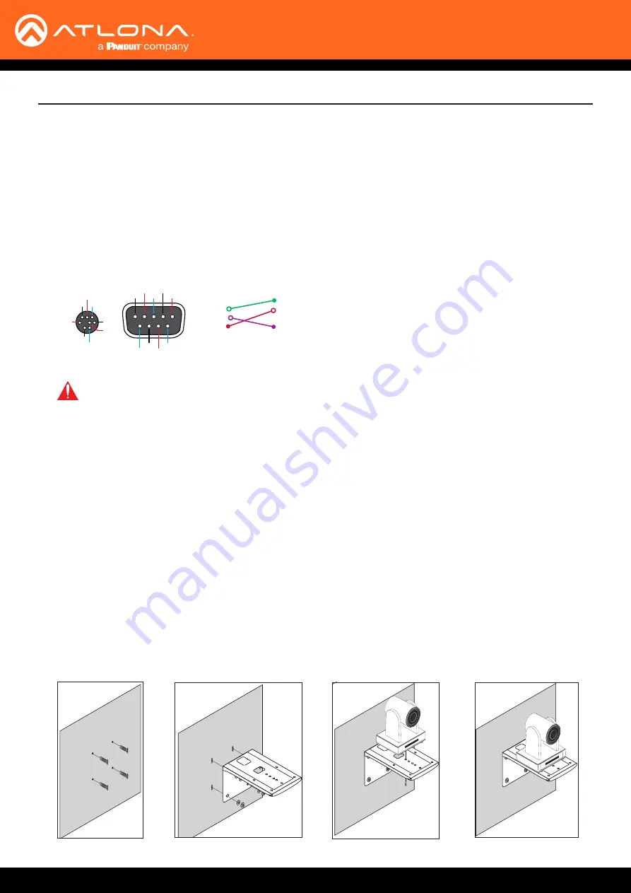
5. *Optional* Connect the Visca to RS-232 cable to the Visca port for RS-232 control. Note that RS-232 can also
be connected to an AT-OME-RX11 or other receiver that supports RS-232 for remote control.
GND
RXD
CTS
TXD
RI
DSR
DSR
RTS
DCD
NC
TXD
DSR
DTR
GND
IR OUT
GND
RXD
Visca
Visca
RS-232
RS-232
DTR
DSR
TXD
GND
RXD
GND
IR OUT
NC
DCD
RXD
TXD
DTR
GND
DSR
RTS
CTS
RI
Connection Instructions
Mounting Instructions
The AT-HDVS-CAM-HDMI has two installation options, wall mount (included) and ceiling mount (purchased
separately).
Wall Mount installation
Install the AT-HDVS-CAM-HDMI, 4 M6 swelling bolts, 1 1/4 20 UNC bolt, 4 M6 nuts & shims, the included wall mount
bracket, and the AT-HDVS-CAM-HDMI are needed.
1. Install the M6 swelling bolts in a rectangular pattern on the wall, 100 mm wide and 50 mm high.
2. Attached the wall mount bracket onto the wall, by placing them on the M6 swelling bolts and securing it with the
M6 nuts and shims.
3. Once the wall mount bracket is secure on the wall, place the camera on the top of the wall mount bracket and
secure it with the 1/4 20 UNC bolt.
1
0
X
Z
o
o
m
F1
.6
-F
3.0
f4.
7m
m
-
f
4
7
m
m
10
X
Z
oom
F1.
6-F
3.
0
-
f
4
7
m
m
1
0
X
Z
o
o
m
F1
.6
-F
3.0
f4.
7m
m
-
f
4
7
m
m
10
X
Z
oom
F1.
6-F
3.
0
-
f
4
7
m
m
1
0
X
Z
o
o
m
F
1.
6-
F3
.0
f4.7
m
m
-
f
4
7
m
m
1
0X
Z
oom
F1.
6-F
3
.0
-
f
4
7
m
m
1
0
X
Z
o
o
m
F
1.
6-
F3
.0
f4.7
m
m
-
f
4
7
m
m
1
0X
Z
oom
F1.
6-F
3
.0
-
f
4
7
m
m
1
0
X
Z
o
o
m
F1
.6
-F
3.0
f4.
7m
m
-
f
4
7
m
m
10
X
Zo
om
F
1.6
-F
3.
0
-
f
4
7
m
m
1
0
X
Z
o
o
m
F1
.6
-F
3.0
f4.
7m
m
-
f
4
7
m
m
10
X
Zo
om
F
1.6
-F
3.
0
-
f
4
7
m
m
1
0
X
Z
o
o
m
F1
.
6-
F3
.0
f4.
7m
m
-
f
4
7
m
m
10
X
Zo
om
F
1.6
-F
3.
0
-
f
4
7
m
m
1
0
X
Z
o
o
m
F1
.
6-
F3
.0
f4.
7m
m
-
f
4
7
m
m
10
X
Zo
om
F
1.6
-F
3.
0
-
f
4
7
m
m
IMPORTANT:
Never disconnect power from the USB host device during operation. Disconnecting
the power from the USB host can cause video instability.


