AT-OMNI-111-WP
9
RS-232
AT-OMNI-111-WP
PWR
HDMI
LINK
RESET
TM
O
MNI
S
TREAM
HDMI IN
ETHERNET
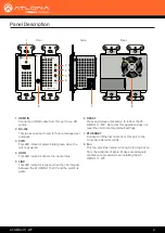
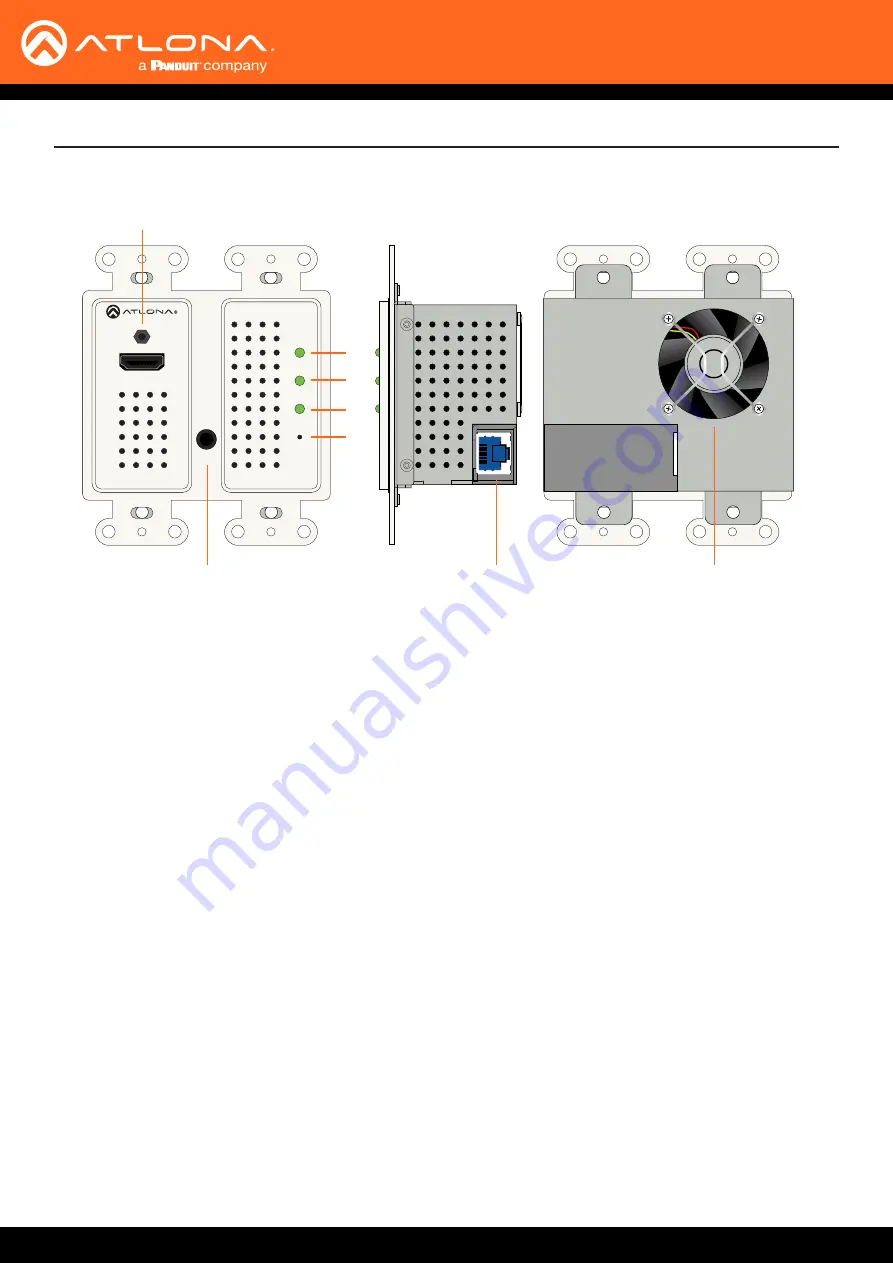
Panel Description
1
2
7
8
3
4
5
6
1
HDMI IN
Connect an HDMI cable from this port to an HD
source.
2 RS-232
This is a service port used for future management
purposes.
3 PWR
This LED indicator glows bright green when the
unit is powered.
4 HDMI
This LED indicator shows the input status.
5 LINK
This LED indicator is green when the link integrity
between the AT-OMNI-111-WP and the switch is
good.
6 RESET
Press and release this button to reboot the AT-
OMNI-111-WP. Note that this operation
does not
reset the unit to factory-default settings.
7 ETHERNET
Connect an Ethernet cable from this port to the
Local Area Network (LAN).
8 Fan
This fan provides internal cooling by forcing hot air
from the wallplate chassis. Make sure adequate
ventilation is provided when installing the AT-
OMNI-111-WP.
Front
Side
Rear


