2
Installation Guide
AT-OME-MH21
1
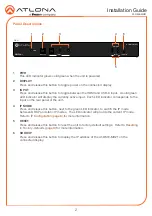
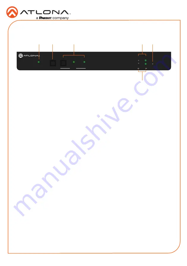
PWR
This LED indicator glows solid green when the unit is powered.
2
DISPLAY
Press and release this button to toggle power on the connected display.
3
INPUT
Press and release this button to toggle between the HDMI and USB-C input. A solid green
LED indicator will display the currently active input. Each LED indicator corresponds to the
input on the rear panel of the unit.
4
IP MODE
Press and release this button, next to the green LED indicator, to switch the IP mode
between DHCP and static IP modes. The LED indicator will provide the current IP mode.
Refer to
for more information.
5
RESET
Press and release this button to reset the unit to factory-default settings. Refer to
for more information.
6
SHOW IP
Press and release this button to display the IP address of the AT-OME-MH21 on the
connected display.
INPUT
2
1
AT-OME-MH21
DC 5V
LAN
IR OUT
RS-232
HOST USB
USB HUB
L
R
-
-
+
+
TX
RX
TX
OUTPUT
PWR
IP MODE
DISPLAY
AT-OME-MH21
OMEGA
TM
RESET
SHOW IP
INPUT
2
1
Panel Descriptions
Front
1
2
3
4
5
6

