5
Installation Guide
AT-OME-MH21
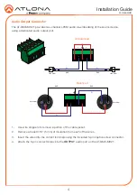
The AT-OME-MH21 provides control using RS-232 and/or IR. This step is optional.
1. Use wire strippers to remove a portion of the cable jacket.
2.
Remove at least 3/16” (5 mm) from the insulation of the RX, TX, and GND wires for the RS-
232 connection.
3.
Insert the TX, RX, and GND wires into correct terminal using one of the included 4-pin
captive screw connectors.
4.
Repeat step 2 for the S and GND wires for the IR connection.
5.
Insert the S (signal) wire in to the TX terminal and the ground wire to the GND terminal.
6. Tighten the captive screws to secure the wires in place. Do not over-tighten or use high-
torque devices to prevent damage to the connector block.
NOTE:
Typical DB9 connectors use pin 2 for TX, pin 3 for RX, and pin 5 for
ground. On some devices functions of pins 2 and 3 are reversed. Note that the
signal (S) pin for the IR is labeled as “TX” on the port.
GND
to control system
or IR emitter
DE-9 (RS-232) port
RX
TX
S
GND
RS-232 and IR
RX TX TX

