AT-OMNI-324
7
HOST
LINK
PWR
O
MNI
S
TREAM
TM
SIGNAL
USB
USB
USB
USB
LAN
PAIRING
UTILITY
AT-OMNI-324
DC 24V
HOST
LINK
PWR
O
MNI
S
TREAM
TM
SIGNAL
USB
USB
USB
USB
LAN
PAIRING
UTILITY
AT-OMNI-324
DC 24V
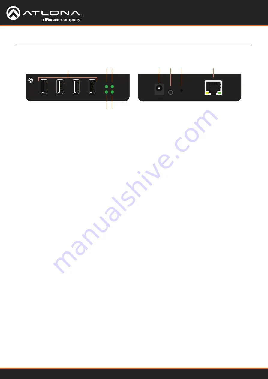
Panel Description
2
1
3
7
6
8
9
4 5
Front
Rear
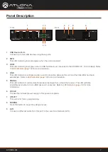
1 USB Device Ports
Connect up to four USB devices using these ports.
2 PWR
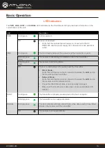
This LED indicator glows solid green when the unit is powered.
3 HOST
This LED indicator glows green when a USB host device is connected to the AT-OMNI-311 (not included). Refer
for more information.
4 LINK
This LED indicator is solid green when a solid connection between this unit and the transmitter has been
established. Refer to
for more information.
5 SIGNAL
This LED indicator monitors data transmission between this unit and the receiver. The LED will blink
intermittently whether or not a USB device is connected. Refer to
for more
information.
6 DC 24V
Connect the included power supply to this power receptacle.
7 UTILITY
This port is for factory programming.
8 PAIRING
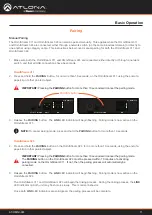
Press this button to begin the pairing process.
9 LAN
Connect an Ethernet cable from this port to the Local Area Network (LAN).


