background image

AT-OMNI-324

8

Installation

Connection Instructions

1. 

Place the AT-OMNI-324 near the location of the USB devices to be connected.  Connect up to four USB devices 

to the USB ports on the AT-OMNI-324.

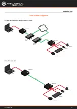
The AT-OMNI-324 can be connected to a AT-OMNI-311 (not included) in one of two ways:

a. 

Connect an Ethernet cable, up to 330 feet (100 meters), from the 

LAN

 port of the 

AT-OMNI-324 directly to the AT-OMNI-311 (not included).


2.  Connect the included power supply to the 

DC 24V

 power receptacle.

3.  Connect the power supply to an available electrical outlet.

4.  Refer t

Pairing (page 11)

 for instructions on pairing.

a. 

Connect an Ethernet cable, up to 330 feet (100 meters), from the 

LAN

 port on the AT-OMNI-324 to the 

network switch.  Note that multiple AT-OMNI-324 units can be connected to the network.

b. 

Connect an Ethernet cable, up to 330 feet (100 meters), from the transmitter (AT-OMNI-311; not included) to 

a switch on the same network.

Over a Network

Direct Connection

NOTE:

 When connecting a transmitter and receiver, over a network, the cable distance between 

hops must not exceed 330 feet (100 meters) for copper connections (fiber extenders can be used 

to create longer runs).  For example, connecting up to five network switches, using copper cabling, 

can be used to extend USB up to 1980 feet (600 meters).

IMPORTANT:

 The AT-OMNI-324 supports a maximum of 3 additional USB hubs that may be 

connected downstream. Up to 7 AT-OMNI-324 units may be paired to an AT-OMNI-311, allowing up 

to a maximum of 31 USB devices.

Summary of Contents for Atlona OmniStream AT-OMNI-324

Page 1: ...AtlonaManuals OmniStream AT OMNI 324 Adapter for Peripheral Devices USB to IP...

Page 2: ...AT OMNI 324 2 Version Information Version Release Date Notes 3 Oct 2023 added spanning tree note to page 8...

Page 3: ...e San Jose CA 95134 United States Office 1 408 962 0515 Sales and Customer Service Hours Monday Friday 6 00 a m 4 30 p m PST https atlona com International Headquarters Atlona International AG To dist...

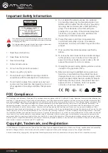
Page 4: ...a tional instructions in the literature accompanying the product Important Safety Information FCC Compliance FCC Compliance and Advisory Statement This hardware device complies with Part 15 of the FCC...

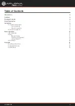
Page 5: ...ection Instructions 8 Over a Network 8 Direct Connection 8 Connection Diagrams 9 Basic Operation 10 LED Indicators 10 Pairing 11 Manual Pairing 11 Unpairing an Extender 12 Using Velocity 12 DHCP Reset...

Page 6: ...t of a fully IP based meeting room system in conjunction with OmniStream AV over IP devices and the Velocity Control System Introduction Features Package Contents Extend USB over Gigabit Ethernet usin...

Page 7: ...o LED Indicators page 10 for more information 4 LINK This LED indicator is solid green when a solid connection between this unit and the transmitter has been established Refer to LED Indicators page 1...

Page 8: ...00 meters from the LAN port on the AT OMNI 324 to the network switch Note that multiple AT OMNI 324 units can be connected to the network b Connect an Ethernet cable up to 330 feet 100 meters from the...

Page 9: ...am Microphone Laptop PW R LIN K SIG NA L HO ST OMN ISTR EA M TM PW R LIN K SIG NA L HO ST OMN ISTR EA M TM LAN Ethernet Ethernet E t h e r n e t U S B AT OMNI 311 AT OMNI 324 Keyboard Mouse Web cam Mi...

Page 10: ...n fast The receiver is in Pairing Mode Off There is no link between the receiver and the transmitter Direct Mode Verify that an Ethernet cable is connected between the LAN port on the receiver and the...

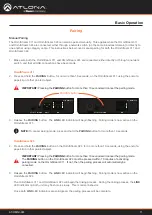
Page 11: ...l pairing for both the OmniStream 311 and OmniStream 324 Manual Pairing PWR LINK SIGNAL HOST OMNISTREAM TM UTILITY PAIRING LAN HOST AT OMNI 311 PAIRING button HOST LINK PWR OMNISTREAM TM SIGNAL USB US...

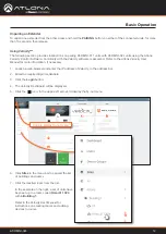
Page 12: ...al for more information if necessary 1 Launch a web browser and enter the IP address of Velocity in the address bar 2 Enter the required login credentials 3 Click the Login button 4 The Velocity Dashb...

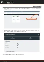
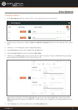
Page 13: ...unpaired two macros will need be created one for pairing and one for unpairing Basic Operation 8 The Modify Room screen will be displayed Click the Room Control Options icon in the upper right corner...

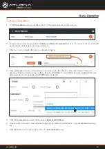
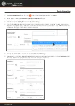
Page 14: ...dialog 4 Click the Device drop down list and select one of the device from this list Since the Unpair macro will disconnect the two units from one another either the AT OMNI 311 or AT OMNI 324 can be...

Page 15: ...st and select the unit to be paired Since the AT OMNI 324 was already selected select the AT OMNI 311 from the drop down list 1 In the Room Macros screen click the icon in the upper right corner of th...

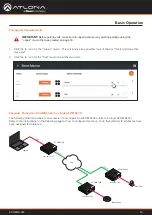
Page 16: ...ring two AT OMNI 324 to a single AT OMNI 311 The following illustration depicts an example of how to pair two AT OMNI 324 units to a single AT OMNI 311 Refer to the instructions on the following page...

Page 17: ...elect one of the devices from this list Since the Unpair macro will be disconnecting a total of three units from one another the Unpair macro will contain a total of three commands In this example the...

Page 18: ...more convenient but does not provide the option of which AT OMNI 324 is paired with the AT OMNI 311 For this example two separate pairing macros will be created 9 Enter Pair to camera in both the Name...

Page 19: ...op down list and select the AT OMNI 324 that is connected to the speakerphone The AT OMNI 324 with the IP address of 192 168 11 123 will be selected 14 Click the Command drop down list and select Pair...

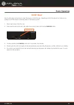
Page 20: ...e unit and within 5 seconds press and hold the PAIRING button 3 Continue holding the PAIRING button for 15 seconds then release 4 Power cycle the unit once again by disconnecting and reconnecting the...

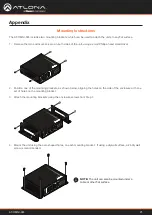
Page 21: ...e enclosure with one set of holes on the mounting bracket 3 Attach the mounting brackets using the enclosure screws from Step 1 4 Mount the unit using the oval shaped holes on each mounting bracket If...

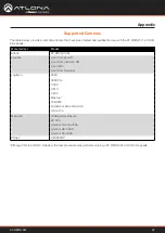
Page 22: ...ce the test procedure was performed using a AT OMNI 324 at USB 2 0 speeds Manufacturer Model Atlona AT HDVS CAM Creative Live Connect HD Live Cam inPerson HD Live Ultra Live Cam Socialize Logitech 900...

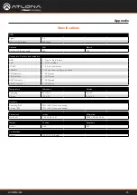
Page 23: ...4 x 3 92 x 3 01 26 40 x 99 50 x 76 45 Weight Pounds Kilograms Device 0 50 0 23 Certifications Device CE FCC CB RoHS Temperature Fahrenheit Celsius Operating 32 to 122 0 to 50 Storage 20 to 70 4 to 158...

Page 24: ...Toll free US International atlona com 877 536 3976 41 43 508 4321 35206 R3...

Reviews: