Battery Pump CT-2902BPHP
HE17600_C © 09/2016
Intended Use
I.VII
authorised
copy
4.1 Operation of the unit
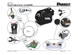
1. The female coupling of the hydraulic hose HSOEL2 must be connected to the male coupling of the pump.
2. Select the right working unit for the intended application.
3. The selected working unit will be connected via the hydraulic hose HSOEL2 with the pump
Attention
Do not operate the pump without a working unit.
Attention
Before starting to operate the pump the oil level must be checked and possibly adjusted.
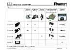
4. Besides the built-in trigger, the following accessories can be connected:
• Remote control CT-2902RPS
• Safety foot switch incl. 4m cable FTA4
• Two hand safety control ZST4)
• Bus bar tool centre and SBZ4
The pump recognizes the various accessories through a special coding; the forward key will be deactivated accor-
dingly.
5. The battery and possibly the spare battery will be plugged into the sockets.
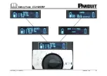
6. The pump is now ready to operate. The LCD display is activated.
7. Select the program for the intended application by turning the selection knob or the data function.
8. The working cycle is initiated by activating the advance function of the ‚forward and return keys‘
Attention
With the SBZ4 connected to pump and bus bar tool center the forward and return keys are deactivated.
Attention
The punching, hole making, crimping and cutting cycle can be stopped at any time by releasing or stepping
down the actuator of the safety foot switch, resp. releasing the the two hand safety switch .
Once the three step safety foot switch has been stepped down, it can only be reactivated by pushing the reset button
of the foot switch. This reset button is located on the top of the foot switch.
After the two hand safety control ZST4 had been activated it must be reactivated by pulling the knob.

