INSTRUCTIONS CM340B
For Instructions in Local Languages
and Technical Support:
www.panduit.com/resources/install_maintain.asp
E-mail:
cs@panduit.com
Fax
:
(708)444-6448
www.panduit.com
Page 28 of 28
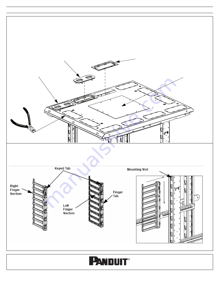
Cable Management Installation
Included in the cabinet are cable management fingers sections (5 Right 5 Left). Cable management can be installed where desired by inserting
the tabs on the rear of the finger sections in the mounting slots slot located on the four (4) cabinet posts and sliding downward. To remove
reverse the process.
Note:
The top mounting tab and mounting slot are keyed to allow proper alignment with rack units
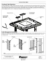
Removable Cover
Overhead Cable
Opening Bezel
Overhead Cable
Opening Bezel
(INSTALLED)
Center Top
Plate
Overhead Cable Openings
Cabinet is equipped with multiple covers and knockouts for cable entry. The center top plate can be removed by removing the four (4) #12-24
screws that hold it in place. Knockouts can be removed by cutting the (8) tabs with a wire cutter as shown. Bezels are to be snapped into posi-
tion where knockouts have been removed, as shown below. The removable covers can be snapped into overhead cable opening bezels.
Grommet edging is provided and is to be used around any knockouts that are removed where bezels and removable covers are not installed.
Grommet edging should be cut to 21” in length to cover the edges of each removed knockout.

