background image

INSTRUCTIONS CM661A

For Instructions in Local Languages

and Technical Support:

www.panduit.com/resources/install_maintain.asp

E-mail:

techsupport@panduit.com

Phone

:

866-405-6654

www.panduit.com

Page 12 of 12

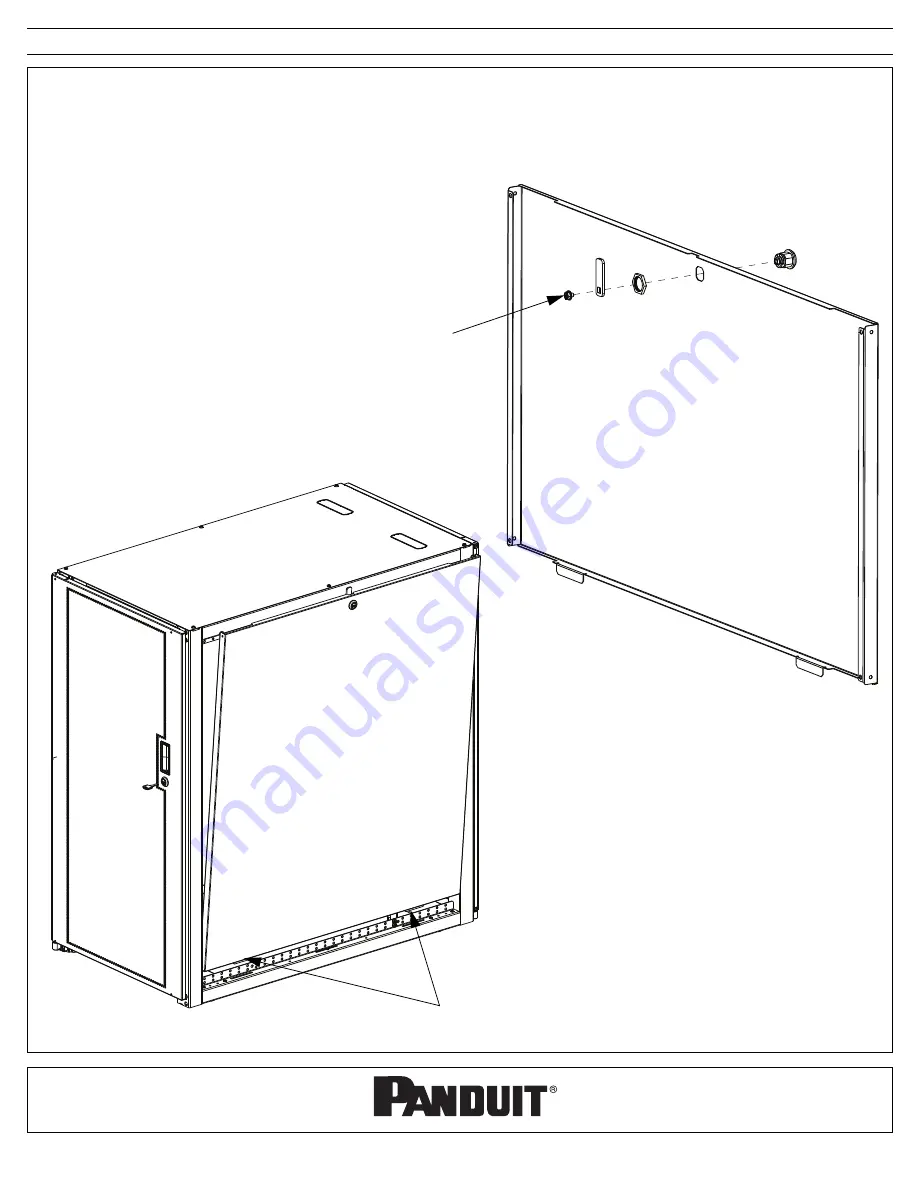
Side Panels (Removal and Installation)

Install [2] Quarter-turn Lock Assemblies (as shown below)

Move Side Panel into place and insert tabs of panel into slots in beam of cabinet frame

Push top of Side Panel towards cabinet frame

Lock Side Panels

REVERSE STEPS to remove Side Panel

Side Panel Tabs

[2] Quarter-turn 
Lock Assemblies
(use Phillips screw-
driver and 27mm 
wrench)

Summary of Contents for E6212B1FP

Page 1: ...STOP READ ALL OF THE FOLLOWING INSTRUCTIONS BEFORE REMOVING CABINETFROM CARTON CM661A...

Page 2: ...of 12 Enterprise Cabinets E6212B1FP E6212B1FP5 E6412B2FP E6412B2FP5 Server Configured NOTE Some views in this document may vary slightly from your actual cabinet configuration Tool List 27mm wrench 2...

Page 3: ...Frame Assembly 4 Leveling Leg and Caster Installation 5 Leveling 6 Equipment Rail Adjustment 7 Top Cap Installation and Overhead Cable Openings 8 Grounding 9 Door Side Panel Bumper Installation 10 Fro...

Page 4: ...Post note diamond cutout Frame Assembly Use 24 M6 Torx Screws to assemble 4 Cabinet Posts to Upper and Lower Cabinet Frame Members ASSEMBLED FRAME Lower Cabinet Frame Member Left Front Post with inte...

Page 5: ...aintain asp Page 5 of 12 Leveling Leg and Caster Installation Install 4 Leveling Legs into cabinet frame to fully retracted position Install 4 Caster Assemblies with 4 Hex Nuts per caster 4 Leveling L...

Page 6: ...et Leveling Side to Side Cabinet Leveling Leveling Ensure that 4 Leveling Legs are fully retracted Roll Cabinet into final position Lower the 4 Leveling Legs until the cabinet weight is fully supporte...

Page 7: ...NOTE Front equipment rails are integral to the cabinet frame and are in a fixed position NOTE Diamond cutouts on cabinet frame indicate mounting holes to allow for 742mm industry standard equipment r...

Page 8: ...with 6 M6 Torx Screws Cut 4 tabs of each Cutout with wire cutter to open each cable opening OPTIONAL NOTE If Cutouts are removed Panduit recommends installing CTCN1X5 Bezel and Cover not included for...

Page 9: ...s install_maintain asp Page 9 of 12 8 Grounding Lug Locations Front and Rear of Beams Grounding Attach Grounding Lug or Grounding Bar at any of the 2 location s shown below Grounding location is indic...

Page 10: ...bber Bumpers on each side panel Install 5 Rubber Bumpers for 24 RU doors or 3 Rubber Bumpers for 12 RU doors on each door NOTE Front Door is indicated by PANDUIT label 4 Rubber Bumpers Rubber Bumper i...

Page 11: ...4 Hinge Brackets to cabinet frame 2 left front 2 right rear with 1 M6 Torx Screw per bracket Open Door s to approximately 90 Lift Door s up and insert hinge pins of door s into hinge brackets REVERSE...

Page 12: ...t com Page 12 of 12 Side Panels Removal and Installation Install 2 Quarter turn Lock Assemblies as shown below Move Side Panel into place and insert tabs of panel into slots in beam of cabinet frame P...

Reviews: