


For Technical Support: www.panduit.com/resources/install_maintain.asp
INSTALLATION INSTRUCTIONS PN256D
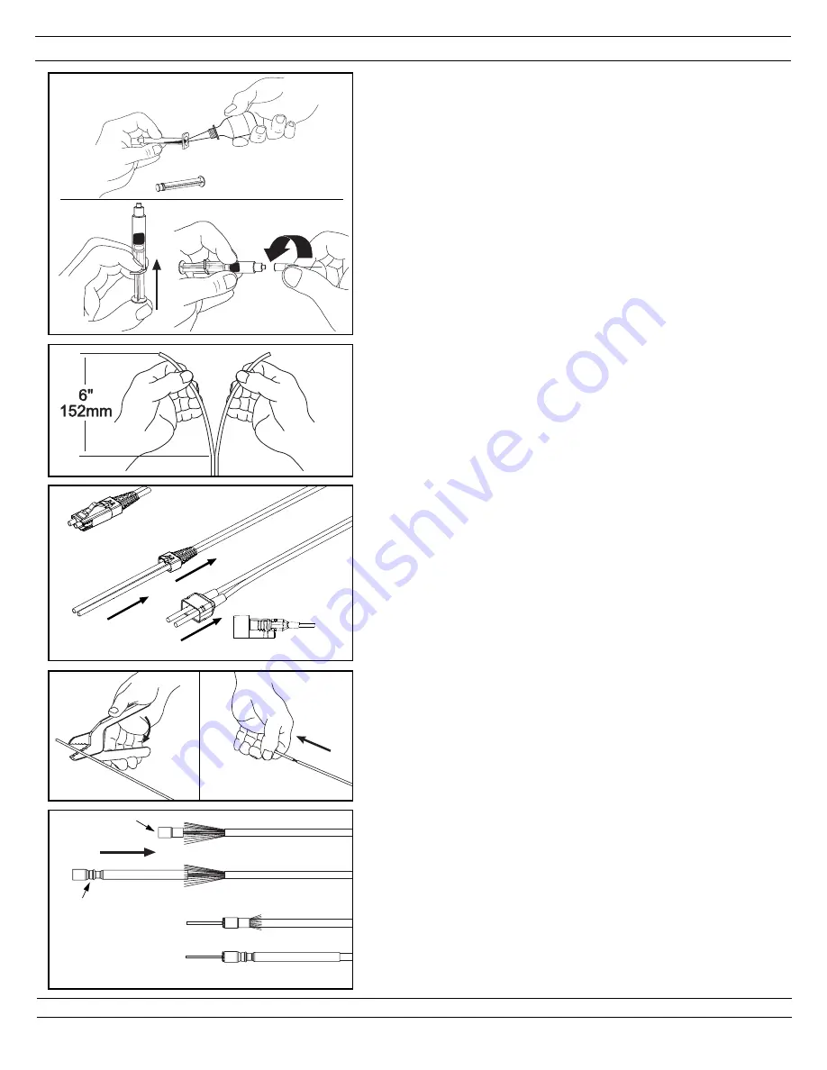
3.2.1
PLUG
JACK
3.2.2
3. FERRULE TERMINATION
3.1 TERMINATION PREPARATION
3.1.1 Remove the plunger from a syringe. Squeeze about 0.5 ml
of FJPXY Anaerobic Adhesive into the back of the syringe
barrel. Insert the plunger. Point opening upward, and
squeeze any air out of the barrel. Attach needle to syringe.
Adhesive that is stored in a syringe may start to harden
within 24 hours.
3.1.2 Partially fill a second syringe with about 0.5ml of FJPMR
Primer. Do this by drawing primer up into the syringe barrel
rather than pouring it in through the back.
3.2 3.0mm/2.0mm/1.6mm JACKET / 900µm BUFFER
STRIPPING
Refer to Page 1 or appropriate
PANDUIT
laminated tem-
plate
for stripping dimensions.
3.2.1
For jacketed duplex cable:
Split the two cables
approximately 6" (152mm) or as needed depending on
desired jacket stripping length.
3.2.2 Insert the fiber end through the small end of the appropriate
boot for your specific fiber type. Slide the boot back out of
the way.
Note: For plug termination only, maintain proper
orientation of the fibers by using the ‘A’ and ‘B’ marks
on the plug insert and boot to your specific wiring
convention.
3.2.3
For jacketed cable only:
To reduce wear on the jacket
stripper blades, do not slide the blades along the aramid
yarn. Instead, use the tool to cut through the jacket, then
pull off the jacket by hand.
For 3.0mm jacketed fiber
, use
the third hole (marked “1.3MM” or #16AWG) from the tip of
the jacket stripper.
For 2.0mm/1.6mm jacketed fiber
, use
the first hole (marked “.80MM” or #20AWG) from the tip of
the jacket stripper. Using the cable jacket stripper, strip the
required length of the jacket off of each fiber according to
the stripping dimensions.
3.2.4
For jacketed cable only:
Insert each fiber through the
smaller end of the crimp sleeve. Use the crimp sleeve to
fold the aramid yarn back over the jacket, holding it out of
the way.
3.2.5
For jacketed cable only:
Use the marking pen and
stripping dimensions provided to mark each buffer from the
end of the jacket.
3.2.6
For 900µm buffered fiber only:
Using the marking pen,
place a mark 1" (25mm) from the end of the buffer.
3.2.7 With the buffer stripper provided, strip the buffer.
3.1.1
ADHESIVE
Page 3 of 8
3.2.3
3.2.4
3.0mm Crimp
Sleeve
2.0mm/1.6mm
Crimp Sleeve
3.0mm Crimp Sleeve
2.0mm/1.6mm Crimp Sleeve


