


For Technical Support: www.panduit.com/resources/install_maintain.asp
INSTALLATION INSTRUCTIONS PN256D
3.4
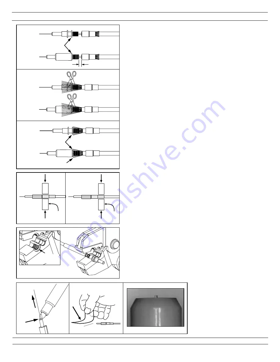
CRIMPING
For jacketed cable only
.
Note: Be careful not to break the bare fibers
protruding from the ferrules during this step.
3.4.1 Slide the crimp sleeve back, freeing the aramid
yarn. The cable jacket should nearly touch the rear
of the backbone of the ferrule assembly.
Note: Do not press the cable jacket forward to
touch the rear of the backbone. There should be
a gap between the jacket and backbone.
3.4.2 With the appropriate strength member (aramid
yarn) cutters, cut the aramid yarn even with the
flange.
3.4.3 Flare the aramid yarn
evenly
around the perimeter
of the grooved area of the backbone of the ferrule
assembly.
For 2.0mm/1.6mm jacketed cable
, use
tweezers for best results.
3.4.4 Slide the crimp sleeve over the backbone, trapping
the aramid yarn between the crimp sleeve and the
grooved area of the backbone.
3.4.5
For 3.0mm jacketed cable:
Make sure the crimp
sleeve is seated against the flange of the backbone,
crimp the large end of the crimp sleeve using a
.151" hex of the FCRP5 Universal Crimp Tool.
Using the .128" hex of the crimp tool, crimp the
small end of the crimp sleeve over the cable jacket.
3.4.6
For 2.0mm/1.6mm jacketed cable:
Align the front
edge of the crimp sleeve with the front recessed
edge of the die pocket of the FLPT crimp tool.
Note:
The front recessed edge of the crimp die
pocket is the side with the ribs.
Make sure the crimp sleeve is seated against the
backbone and crimp the crimp sleeve.
3.4.7 Repeat for the second ferrule assembly.
3.5 CLEAVING
3.5.1 Using a cleave tool, gently make one small score
mark across the bare fiber just above the endface of
the ferrule. Pull the fiber away from the ferrule and
discard it on one of the sticky tabs provided. A
short stub of fiber protruding from the tip of the
ferrule should be visible when viewed through the
FLOUPEX10 Eye Loupe.
3.5.2 Repeat for the second ferrule assembly.
Page 5 of 8
3.4.1
FLARE ARAMID
YARN EVENLY
FLANGE
GAP
3.4.3
JACK
PLUG
JACK
PLUG
JACK
PLUG
3.4.2
FLANGE
FIRST
CRIMP
SECOND
CRIMP
3.4.5
.151" HEX
DIE
.
128" HEX
DIE
3.4.5
3.4.6
Recessed
Edge
Crimp die
1. SCORE
2. PULL
FIBER
3.5.1


