background image

For Technical Support: www.panduit.com/resources/install_maintain.asp

INSTALLATION INSTRUCTIONS     PN256D

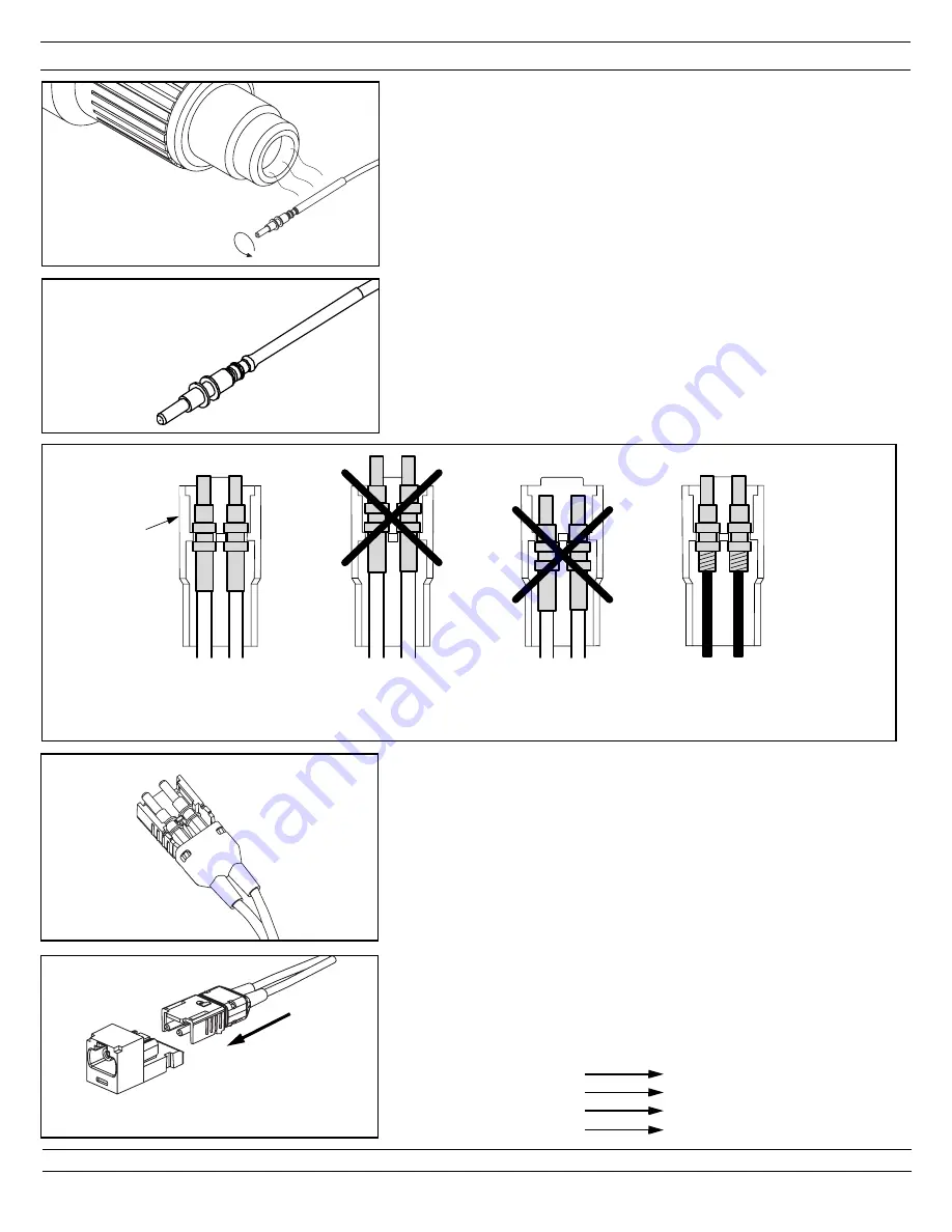
5. CURING HEAT SHRINK TUBING

For 2.0mm/1.6mm jacketed cable only

.

5.1

Turn the heat adjustment knob of the heat shrink curing 
tool so the white line is centered in the notch.

5.2

Turn heat shrink curing tool “on”. (The temperature of the 
hot air stream at the nozzle should be 220°F - 240°F)

5.3

Hold onto the connector and support the cable.

5.4

Bring the heat shrink tubing into the hot air stream. Hold 
the heat shrink tubing about 1/2" away from the nozzle. 
Rotate the connector for 20-30 seconds so that the heat 
shrink tubing is completely cured onto the jacket.

5.5

Remove the connector from the hot air stream.

5.6

Turn heat shrink curing tool “off”.

Page 7 of 8

6. JACK ASSEMBLY

6.1

Turn the snap-on jack cover over in your hand so that the ‘A’ 
and ‘B’ marks inside the cover are facing you and are 
upright.  Then, place each ferrule assembly in the jack 
cover.  Maintain proper orientation of the fiber runs by using 
the ‘A’ and ‘B’ marks to your specific wiring convention.

6.2

Slide the boot up to the cover until the holes of the boot lock 
on to the tabs of the cover.

6.3

Next, position snap-on jack cover behind the jack housing. 
The ferrules should start to enter the split sleeves which are 
held within the jack housing. Slide cover forward, aligning 
the rails in the cover and jack housing.                                                                           

Note: If you are using 

O

PTI

-J

ACK

 Keyed connectors, 

verify that plug mates with intended jack.


6.1

SLIDE
FORWARD

6.3

5.5

YES

Jacketed Cable

NO

Ferrules are located

too far forward

NO

Ferrules are located

too far backward

YES

Buffered Cable

6.1

Jack Cover

5.4

FJEPGM5CWBL
FJEPGM5CXRD
FJEPGM5CYOR
FJEPGM5CZYL

FJJGM5CWBL
FJJGM5CXRD
FJJGM5CYOR
FJJGM5CZYL

Summary of Contents for FJJGM2.0C

Page 1: ...ETED STRIPPING DIMENSIONS 1 5 JACKETED STRIPPING DIMENSIONS 1 3 900 m BUFFERED STRIPPING DIMENSIONS 1 1 JACK ASSEMBLY JACK 1 4 PLUG ASSEMBLY PLUG IMPORTANT Due to printing variations use a rigid or th...

Page 2: ...e connector or when han dling bare optical fiber The bare fiber is very sharp and can easily damage the eye 2 2 ISOPROPYL ALCOHOL WARNING Isopropyl alcohol is flammable Contact with the alcohol can ca...

Page 3: ...maintain proper orientation of the fibers by using the A and B marks on the plug insert and boot to your specific wiring convention 3 2 3 For jacketed cable only To reduce wear on the jacket stripper...

Page 4: ...h the ferrule in a smooth forward motion The fiber is fully inserted when the buffer bottoms against the rear of the ferrule The adhesive will begin to set within seconds Note If adhesive oozes out th...

Page 5: ...t the flange of the backbone crimp the large end of the crimp sleeve using a 151 hex of the FCRP5 Universal Crimp Tool Using the 128 hex of the crimp tool crimp the small end of the crimp sleeve over...

Page 6: ...Clean the ferrule tip pad and bottom of the puck with an alcohol soaked wipe 4 5 Place a sheet of 1 m diamond polishing film onto the polishing pad Place several drops of distilled water on the diamon...

Page 7: ...JACK ASSEMBLY 6 1 Turn the snap on jack cover over in your hand so that the A and B marks inside the cover are facing you and are upright Then place each ferrule assembly in the jack cover Maintain p...

Page 8: ...of the insert Be careful not to pinch the cable The A and B on the insert should line up with the A and B on the boot 7 2 Slide the insert inside the boot until the tabs on the insert lock into the ho...

Reviews: