background image

INSTALLATION INSTRUCTIONS                                                           CM501A

 © Panduit Corp. 2010

For Technical Support: www.panduit.com/resources/install_maintain.asp

PZWC35

(door removed from

(4)#8-32 X 1/4” Screws
(2)Keys

List of Hardware Components (PZWC35 and PZWC35e):

Mounting Plate for 
Wireless Access Point 
Installation (included)

Knockouts
for Surface
Raceway

#10-32 threaded
Grounding Studs and 
Grounding Wire (included)

Double Knockout for 1/2” or 3/4”
Conduit (3 Places)

Keyed Knockout Slots for Wall
Mount applications (6 places)

Key

Key

PZWC35e

view for clarity)

Knockout view (applies to PZWC35 and PZWC35e)

PZWC35

#10-32 threaded
Grounding Studs and 
Grounding Wire (included)

Mounting Plate for 
Wireless Access Point 
Installation (included)

Knockouts for Wireless 
Access Point Antennae

Knockouts
for Surface
Raceway

PZWC35e

P

AN

Z

ONE


Wireless Access Point Enclosure

Page 1 of 6

TABLE OF CONTENTS


Page (s)

Mounting Guide................................................................................................................. 2-4
Wireless Access Point Installation..................................................................................... 5-6

Part Number: PZWC35, PZWC35e

Summary of Contents for PANZONE PZWC35

Page 1: ...ncluded Double Knockout for 1 2 or 3 4 Conduit 3 Places Keyed Knockout Slots for Wall Mount applications 6 places Key Key PZWC35e view for clarity Knockout view applies to PZWC35 and PZWC35e PZWC35 10 32 threaded Grounding Studs and Grounding Wire included Mounting Plate for Wireless Access Point Installation included Knockouts for Wireless Access Point Antennae Knockouts for Surface Raceway PZWC3...

Page 2: ...opening accommodates PANDUIT LD10 surface raceway 1 2 Locate the wall studs Position the enclosure on the wall and identify which keyed knockouts should be removed It is recommended that two of the mounting holes be aligned with the wall stud Wall anchors not included should be used for each additional mounting hole chosen by the installer Remove desired knockouts Optional Flexible grommet edging ...

Page 3: ...1 When the enclosure will be mounted in a suspended ceiling a square hole that is approximately 12 1 2 x 14 1 4 must be cut in the ceiling tile 4 2 It is important that the hole be no smaller than 12 1 4 x 14 and no larger than 12 3 4 x 14 1 2 This will ease instal lation and prevent visible gaps around the enclosure once installed Note The bottom edges of the assembled enclosure brackets can be u...

Page 4: ...t a 90 angle approximately 2 1 2 above the surface of the ceiling tile Repeat this step for the remaining 3 hanger wires measuring to the three remaining corners of the square opening 6 7 Insert the enclosure into the cut ceiling tile opening 6 8 While holding the enclosure flush with the surface of the ceiling tile route the hanger wire through one of the eight 3 8 dia hanger wire mounting holes ...

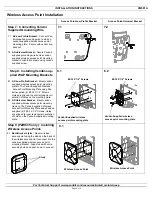
Page 5: ...outer rectangular ori entation of holes on the mounting plate 8 2 AP Universal Bracket Mount vendor supplied wireless access point mounting frame to The Panduit supplied Wireless Access Point Mounting Plate using Panduit supplied 4 8 32 X 1 4 Screws Holes are aligned to inner rectangular orientation of holes on the Panduit supplied mounting plate 8 32 X 1 4 Screws Vendor Supplied wireless access p...

Page 6: ...enclosure base 10 3 Secure with the Nuts and Washers that are on the stud 10 Wire vendor supplied Stud PZWC35 with completed Wireless Access Point Assembly PZWC35e with completed Wireless Access Point Assembly PZWE35 shown 9 1 Both Bracket styles Mount wireless access point using the studs on the back of the wireless access point to connect it to the vendor supplied wireless access point mounting ...

Reviews: