PAT1M / PAT1.5M OPERATION MANUAL
PAT1M/PAT1.5M: PA22222A01_03
Page: 7 of 36
Dec., 2007
INSTALLATION CHECKLIST
1.
Have you made sure that the air supply is NON-LUBRICATED (from any source)?
2. Is the main air supply hose to the dispenser clean and sized properly? (3/8" inside diameter minimum, 10'-0"
(3 m) length maximum from filter/regulator to dispenser)
3. Is the filter element rating correct? (40 micron maximum)
4. Is the filter/regulator equivalent to recommended? (See Page 5.)
5. Are the quick-connect fittings equivalent to recommended? (See Page 5.)
6. Is the filter/regulator located as close to the dispenser as possible? (10' - 0" (3 m) maximum)
7. Is the dispenser placed or mounted in a convenient location? (Refer to the
Dispenser Mounting
section on Page 6.)
8. Is the regulated air line pressure to dispenser sufficient? (Refer to the
Air Supply
section on Page 5.)
LOADING PROCEDURE
1. Attach the XMR Reel Mount Assembly (See Figure 1) to the back of the dispenser (with reel axle facing the front
of the dispenser) by positioning the larger holes in the reel mount assembly over the cap screws on the
dispenser, and sliding the reel mount assembly into position. Tighten the cap screws to fasten the reel mount in
position.
2. Plug the supplied electric cord into the receptacle on the back of the dispenser (See Figure 1). Plug the other
end into a grounded electrical outlet that matches the dispenser power requirements (Refer to the
Electrical
Specifications
section on Page 5). Set the power switch on the back of the dispenser (See Figure 1) to the "on"
position.
IMPORTANT:
Only turn the power to the unit "on" or "off" using the power switch on the back of the dispenser.
Using any other method to turn the unit "on" or "off" may damage the unit.
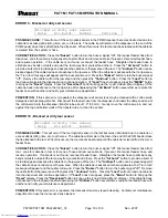
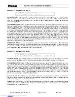
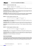
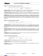
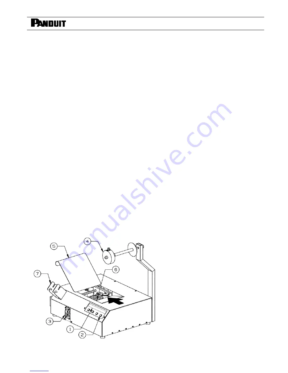
The dispenser rotary receiver (Figure 2) will rotate slightly to align itself and the message "
PANDUIT
-- Tool is
ready" will appear on the electronic display (Figure 2) for two seconds. The dispenser is now ready for loading.
PDM DISPENSER
COMPONENT LIST
1. LCD Display
2. Display Menu Buttons
3. Feeder Hose Connection Block
4. Reel Collar
5. Tie Guide Door
6. Rotary Receiver
7. Tool Holder Bracket
Fig. 2
electronic components distributor


