PAT1M / PAT1.5M OPERATION MANUAL
PAT1M/PAT1.5M: PA22222A01_03
Page: 6 of 36
Dec., 2007
OTHER SPECIFICATIONS
ITEM
DESCRIPTION
Peak Sound Level during cycle
76 dBA (average)*
PAT1M/PAT1.5M Tool Vibration
Less than 2.5 m/s
2
**
* As measured in accordance with ISO 11202: 1995 (E).
** As measured in accordance with ISO 5349.
INSTALLATION
DISPENSER MOUNTING
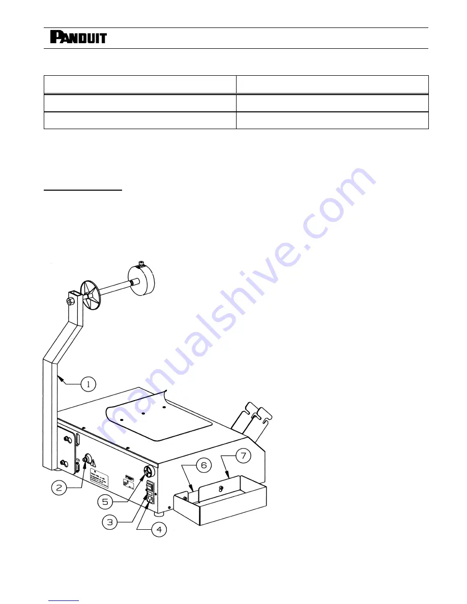
After unpacking the components, mount the carrier strip scrap bin (See Figure 1) on the left side of the dispenser by
positioning the larger holes in the bin over the cap screws on the dispenser, and sliding the bin down. Attach the tool
holder bracket (See Figure 2 on Page 7) to the front of the dispenser by positioning the larger holes in the tool holder
bracket over the cap screws on the
dispenser, and sliding the bracket
down into position. Refer to Page 26
for alternate mounting to walls, carts
or bench tops. Always position the
dispenser in the work area so there
are no severe bends or twists in the
PHM Feeder Hose.
SYSTEM CONNECTION
1. Connect the female quick
disconnect end of the air hose
and filter/regulator assembly to
the male air inlet on the back of
the dispenser (See Figure 1).
2. Connect the filter/regulator to the
main (NON-LUBRICATED) air
supply and set the filter regulator
at 65 PSIG for optimum
performance (Refer to the
Air
Supply
section on Page 5).
3. Verify installation by reviewing the
Installation Checklist
section
below.
PDM DISPENSER
COMPONENT LIST
1.
XMR Reel Mount Assembly
2.
Male Air Inlet
3.
Power Switch/Fuse Holder
4.
Power Cord Receptacle
5. Buzzer/Volume
Adjustment
6.
Carrier Strip Exit Chute
7.
Carrier Strip Scrap Bin
Fig. 1
electronic components distributor


