background image

© Panduit Corp. 2013 

OPERATION MANUAL 

PAT1M, PAT1.5M, PDM 
ENGLISH 


Page: 26 of 39


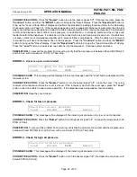
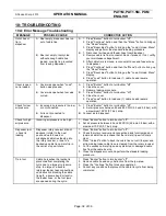
CORRECTIVE ACTION:

  When this occurs, the message will disappear when the switch (button #1, 2, 3, 4, or the 

trigger) has been freed or released.  If the "Switch #X is stuck or broken” message does not disappear, then the 
specific switch (button #1, 2, 3, 4, or the trigger) is bad.  Contact your maintenance department to have the switch 
replaced. 
 

PREVENTION: 

 To prevent this problem from recurring, do not press or hold down any switches (button #1, 2, 3, 4, 

or the trigger) when turning the dispenser power “on”. 


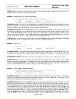
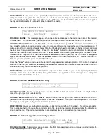
Problem 3 - Restore past tool count


Restore past tool count?


 Mem Off


Yes


No


POSSIBLE CAUSE:

  This message may appear if the tool counter is no longer functioning. 


CORRECTIVE ACTION:

  Press the 

"Yes"

 button and resume operation. 


PREVENTION: 

 If the same error is repeated, press the 

"Mem off"

 button and resume operation.  Notify your 

maintenance department. 


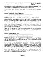
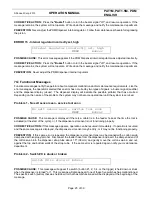
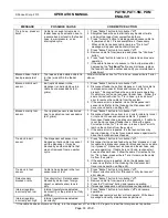
Problem 4 - Jaw sensor error


Jaw sensor error


 Help


Buzzer


Continue


POSSIBLE CAUSE:


A build up of debris in the tool gears caused by not emptying the tip collector often enough. 

 
CORRECTIVE ACTION:  

Press the 

"Buzzer"

 button to turn the buzzer signal "off".  Remove the cable tie and any 

obstruction from the jaw and exit areas of the tool, and empty the tip collector.  Press the continue button and resume 
operation. 
 

PREVENTION:

 Always empty the tip collector before it is full (no more than 180 cycles).  Keeping the tip collector 

clear will allow the cable ties an area to exit the tool.  The tool should also be cleaned periodically by your 
maintenance department.


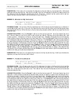
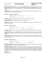
Problem 5 - System error #X


System error #X


 Help


Mem off


Continue


POSSIBLE CAUSE:

  There are 5 different functional messages that may appear.  System error #1, #2, #3, #4, and 

#5 will appear if an internal electronic component malfunctions. 
 

CORRECTIVE ACTION:

  For System errors #1 and #2, write down the system error number and notify your 

maintenance department immediately.  For System errors #3, #4, and #5, toggle the power switch (turn the power 
“off” and then back “on” again) to reset the system.  If the message disappears, resume operation.  If the message 
still appears, press the 

"Continue"

 button and resume operation.  If the System error message does not disappear, 

do not resume operation.  Write down the system error number and notify your maintenance department 
immediately.    
 

PREVENTION:

  None. 


Summary of Contents for PDM

Page 1: ...Automatic Cable Tie Installation Tools PDM Dispenser PHM Feeder Hoses WARNING TO REDUCE THE RISK OF INJURY USER MUST READ INSTRUCTION MANUAL Website www panduit com Email techsupport panduit com EU W...

Page 2: ...Panduit Corp 2013 OPERATION MANUAL PAT1M PAT1 5M PDM ENGLISH DECLARATION OF CONFORMITY...

Page 3: ...Panduit Corp 2013 OPERATION MANUAL PAT1M PAT1 5M PDM ENGLISH...

Page 4: ...HNICAL SPECIFICATIONS 8 5A Air Supply 8 5B Electrical Specifications 8 5C Noise Emission 9 5D Vibration 9 6 INSTALLATION 10 6A Dispenser Mounting 10 6B System Connection 10 6C Installation Checklist 1...

Page 5: ...10A Error Message Troubleshooting 32 10B Functional Message Troubleshooting 34 10C Cable Tie Installation Troubleshooting 34 11 QUICK REFERENCE MENUS 35 11A Operator Menus 35 11B Setup Menus 35 12 ER...

Page 6: ...PAT1 5M Tool NOTE Any substitution may cause serious damage to the system and or injury to the operator 2A PAT1M PAT1 5M Tools The PAT1M and PAT1 5M Cable Tie Installation Tools are electrically power...

Page 7: ...strip scrap bin is also included to collect the carrier strip remaining scrap as the cable ties are detached from the continuous strand Overall System Dispenser w scrap bin Reel Mount and Cable Tie R...

Page 8: ...ncluded on the opposite end of the hose for connection to the dispenser 3 GENERAL POWER TOOL SAFETY WARNINGS The PAT1M PAT1 5M System is pneumatically and electrically operated and electronically cont...

Page 9: ...g must be inserted into a matching outlet that is properly installed and grounded in accordance with all local codes and ordinances DO NOT modify the plug provided If it will not fit the outlet have t...

Page 10: ...alified maintenance personnel Disconnect power cable when replacing components Dangerous voltages may exist even with the power cable removed To avoid injuries always disconnect power and discharge ci...

Page 11: ...l may result in personal injury 4 Do not overreach Keep proper footing and balance at all times This enables better control of the power tool in unexpected situations 5 Dress properly Do not wear loos...

Page 12: ...he safety of the power tool is maintained 4 FCC EMISSION CLASSIFICATIONS USA FCC Emissions for Class A This device complies with part 15 of the FCC Rules Operation is subject to the following two cond...

Page 13: ...ir supply hose from filter regulator to dispenser supplied by user Recommended source Panduit Part Number PDH10 37 See Page 3 Recommended female quick disconnect for main air supply supplied by user T...

Page 14: ...hat the declared vibration total value has been measured in accordance with a standard test method and may be used for comparing one tool with another That the declared vibration total value may also...

Page 15: ...mounting to walls carts or bench tops Always position the dispenser in the work area so there are no severe bends or twists in the PHM Feeder Hose 6B System Connection 1 Connect the female quick disc...

Page 16: ...eel axle facing the front of the dispenser by positioning the larger holes in the reel mount assembly over the cap screws on the dispenser and sliding the reel mount assembly into position Tighten the...

Page 17: ...OLD the Load button until 13 more cable ties are fed As each cable tie is loaded the number next to Load will decrease for each cable tie loaded The dispenser cover must be closed and latched to load...

Page 18: ...n Page 16 1 Plug the supplied electric cord into the receptacle on the back of the dispenser Plug the other end into a grounded electrical outlet that matches the dispenser power requirements Refer to...

Page 19: ...els Level 3 thru Level 6 are not required except to set or to adjust the unit and are reached by the following sequence a Verify that the Level 2 menu is on the display b Press the second button from...

Page 20: ...teps 3 a and 3 b to re enter the higher menu levels Level 3 thru Level 6 LEVEL 5 Line Pressure Menu View line pressure Pressure Escape Menu Exit 5 Press the Pressure button to view the current pressur...

Page 21: ...button to return directly to Level 1 or 1B Operator Menus See Step 1 The MENU button is unavailable since Level 6 is the last Setup menu Press the Exit button to return to the last menu level Level 5...

Page 22: ...sioned and cut off 5 At the completion of the cycle release the trigger to open the rear jaw See Fig 5 on Page 10 Relocate the tool at the next desired cable tie location and repeat as required NOTE I...

Page 23: ...toffs may result Always allow enough space between cable ties and other objects so that the tool can move freely toward the bundle as the cable tie is pulled tight Store the cable ties properly accord...

Page 24: ...by turning the faceplate of the buzzer The buzzer is located on the back of the PDM Dispenser next to the power switch For each error message that appears there will be at least three 3 buttons to ch...

Page 25: ...revent this problem from recurring verify that the air pressure is between 65 and 85 PSIG 4 5 and 5 8 bar with a maximum 10 PSI 0 7 bar drop ERROR 2 Cover is open no tie loaded Cover is open no tie lo...

Page 26: ...able tie path a severe bend or twist in the feeder hose or the tool jaws are opened during the cycle CORRECTIVE ACTION Remove the cable tie and any obstruction from the jaw area Resume operation PREVE...

Page 27: ...ore resuming operation Stay within recommended line pressures and remove any sharp bends in the feeder hose DO NOT drop additional ties in hose to verify that the hose is clear The additional tie will...

Page 28: ...splay Press the Reset load button to bring up the Load Unload Menu display If the cable tie does not advance to the tool jaw area after depressing the Air Burst button several times replace the feeder...

Page 29: ...gnal off Remove the cable tie from the jaw area and then press the Continue button Press the Load button to load one cable tie into the dispenser and continue operation If the cable tie does not advan...

Page 30: ...ture of the problem the system may not become operational until the system is serviced Problem 1 No exit sensor seen service tool soon No exit sensor seen service tool soon MENU Buzzer POSSIBLE CAUSE...

Page 31: ...ctor often enough CORRECTIVE ACTION Press the Buzzer button to turn the buzzer signal off Remove the cable tie and any obstruction from the jaw and exit areas of the tool and empty the tip collector P...

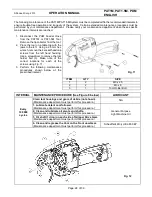
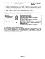
Page 32: ...8A Daily Preventive Maintenance The following maintenance of the PAT1M PAT1 5M System must be performed daily as needed to ensure optimum performance and trouble free operation of the system INTERVAL...

Page 33: ...o remove the tool holder bolt 3 Make note of the correct locations for each of the screws using Fig 11 3 Perform the following maintenance procedures shown below at the prescribed interval ITEM QTY SI...

Page 34: ...ANCE PROCEDURE Every 250 000 cycles 50 cable tie reels PAT1M PAT1 5M Replace tool transfer tube if worn Maintenance department must perform this procedure Every 500 000 cycles 100 cable tie reels PAT1...

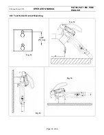
Page 35: ...Panduit Corp 2013 OPERATION MANUAL PAT1M PAT1 5M PDM ENGLISH Page 30 of 39 8D Tool Holder Bracket Mounting Fig 13 Fig 14 Fig 15 Fig 16...

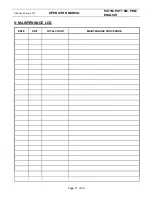
Page 36: ...Panduit Corp 2013 OPERATION MANUAL PAT1M PAT1 5M PDM ENGLISH Page 31 of 39 9 MAINTENANCE LOG DATE UNIT TOTAL COUNT MAINTENANCE PROCEDURE...

Page 37: ...not connected to dispenser A 1 Press Buzzer button to turn buzzer off 2 Set air pressure between 65 and 85 PSIG 4 5 and 5 8 bar with a maximum 10 PSI 0 7 bar drop B Connect air to dispenser Check for...

Page 38: ...der hose from tool Look for cable tie in tool or tool end of hose and remove cable tie if present Reconnect feeder hose and resume operation If cable tie is not found reconnect feeder hose Follow the...

Page 39: ...usly installed tie harness support or other object on bundle E Tool is pulled on as the tie is being tensioned A Increase tool tension setting B Hold tool perpendicular to bundle in both directions C...

Page 40: ...2 Resets install tie counter BUTTON 3 Inactive BUTTON 4 Returns to LEVEL 1 11B Setup Menus LEVEL 2 SETUP MENU ACCESS Resets load and or counter 1 Press BUTTON 3 two times Reset Ld Reset Ct Exit 2 Pre...

Page 41: ...it BUTTON 2 Clears present readings BUTTON 3 Inactive BUTTON 4 Returns to LEVEL 5 LEVEL 6 Language Menu Set language BUTTON 1 Brings up LEVEL 6A Language Escape Exit BUTTON 2 Returns to LEVEL 1 or 1B...

Page 42: ...f problem persists contact Maintenance Department Blocked or Dirty Tool Sensor or Tie Stuck in Tool Sensor a Press Buzzer button then Air Burst button remove cable tie from jaws of tool Press Menu but...

Page 43: ...d or Dirty Blocked Hose Failed Back Pressure Test 12A Cable Tie Condition Factors INCORRECT CABLE TIE CUT OFF Long cut off tail CORRECT CABLE TIE CUT OFF CABLE TIE DETACHES FROM BUNDLE Cable ties are...

Page 44: ...rop too large of a bundle improper feeder hose connections an obstruction blocking the cable tie path a severe bend or twist in the feeder hose or the tool jaws are opened during the cycle CORRECTIVE...

Reviews: