background image

PAT 4.0 AUTOMATIC CABLE TIE INSTALLATION SYSTEM 

ELECTRONIC INTERFACE USER MANUAL 

© Panduit Corp. 2017 


PA28091A01_02 

Page 

8

 of 

2-2017 

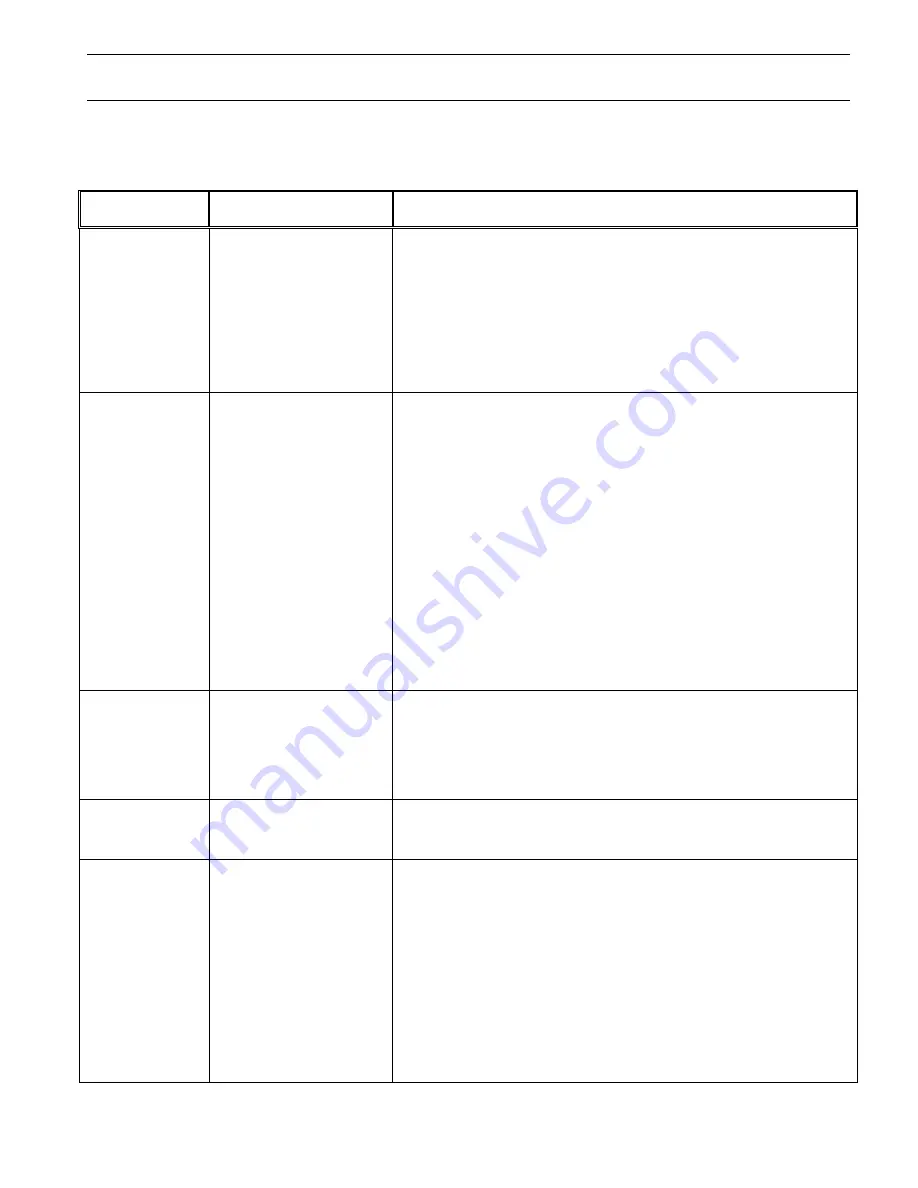
Cable Tie Dispenser Display for Errors & Corrective Action 


Dispenser 

Display


Possible Cause 

Corrective Action 

“Dispenser jam -  
check tie loading” 

Dispenser rotary receiver 
did not advance next tie 
into position; due to bent 
cable tie, or jam of carrier 
strip in strip exit chute. 
{

PDS-EI


Only

: Or Cable  

Tie Reel Moved off of Reel 
Pivot Disk on Dispenser 
Frame} 

1. 

Press "Buzzer" button to turn buzzer off.   

2. 

Check rotary receiver and connection block for jammed cable tie, and 
check for jam in carrier strip exit chute.  

3. 

Press "Unload" to back loose cable ties from rotary receiver & un-jam. 

4. 

Cut excess carrier strip and any distorted or damaged cable ties from 
cable tie reel. 

5. 

Close Cover and perform loading procedure. 

“Out of ties or tie  
in dispenser” 

A. Reel empty; dispenser 
out of cable ties. 
 
 
B. Reel not empty; tool  
     cycled without enough  
     cable ties loaded,  
   
C. Cable tie prevented  
     from leaving dispenser. 


A. 1. Press "Buzzer" button to turn buzzer off. 

2. Press "Continue"; then "Menu" to bring up "Reset" display. 
3. Press "Reset load" to bring up "Load, Unload, Menu" display and 

perform the standard reloading procedure.  

B. 1. Press "Buzzer" button to turn buzzer off. 

2. Press "Continue"; then "Menu" to bring up "Reset" display. 
3. Press "Reset load" to bring up "Load, Unload, Menu" display. 
4. Press "Load" to load one (1) cable tie and resume operation.  

C. 1. Disconnect air hose and feeder hose from dispenser.  

2. Remove cable tie from Dispenser connector block, if present. (if tie 

does not come out freely, turn dispenser off / then on again, to reset 
rotary receiver position).  If not able to remove a stuck tie, notify your 
maintenance department.  

3. After Cable Tie is removed, reconnect air hose and feeder hose to 

dispenser.  

4. Press "Continue"; then "Menu" button to bring up "Reset" display.  
5. Press "Reset load" to bring up "Load, Unload, Menu" display.  
6. Press "Load" to load one (1) cable tie and resume operation. 

“Cover is open, no 
tie loaded” 

A.  Cover was open when  
      "Load" was pressed. 
B.  Cover was open when  
      tool was cycled. 

A.  1. Press "Buzzer" button to turn buzzer off. 

2. Close Cover.  
3. Resume loading procedure. 

B.  1. Press "Buzzer" to turn buzzer off.  

2. Close Cover. 
3. Press "Load" to load one (1) cable tie and resume operation. 

“Check for low air 
pressure” (

or


“high”) 

A. Incoming air pressure  
     too low or too high.  
B. Air not connected. 

A.   1. Press "Buzzer" button to turn buzzer off.    2. Set air pressure 65-85  

PSIG (4.5-5.8 bar), with max. 10 PSIG (0.7 bar) drop.  

B.   Connect air to PDM. 

“Tie stuck in exit 
sensor” 

or  

“Blocked or dirty 
exit sensor” 

or  

“No exit sensor  
seen – service 
tool soon” 

Exit sensor in dispenser is 
obstructed by a cable tie or 
excess debris (dirt, grime). 
                

 or 

Cable tie in feeder hose 
when cycle started. 
                

or 

Exit sensor in dispenser is 
not functioning properly.  


1. Press "Buzzer" button to turn buzzer off.  
2. Disconnect feeder hose from dispenser and remove tie from dispenser  

connector block if present (if tie does not come out freely, turn  
dispenser off / then on again, to reset rotary receiver position). If not  
able to remove a stuck tie, notify your maintenance department.   

3. Reconnect feeder hose, and resume operation.  
4.  If tie is not found, reconnect feeder hose and follow the same  

Corrective Action for "Tie in hose - press air burst" error to remove  
the cable tie from the system.   

5. If the same error is repeated, clean the dispenser exit sensor lens and  

resume operation. 

6. If the same error is still repeated, maintenance is required to replace the 

exit sensor.  


Summary of Contents for PDM4.0 EI

Page 1: ...penser PHM Feeder Hoses Operation Manual PA27647A01 PDM4 0 Data Manager Operations Manual PA25060A01 EI I O port 25 Pin Connector is internally connected to Optically Isolated Modules WARNING TO REDUCE THE RISK OF INJURY USER MUST READ INSTRUCTION MANUAL Email techsupport panduit com EU Website www panduit com emea EU Email emeatoolservicecenter panduit com www panduit com Panduit Corp Tinley Park...

Page 2: ... and updated Consequently pictures may vary from the enclosed product 2 SYSTEM SPECIFICATIONS The Panduit Corporation PAT Cable Tie Installation System consists of four compatible units the PAT Installation Tool the PDM Dispenser the PHM Feeder Hose and Panduit Pan Ty XMR Cable Ties Cable ties are available in reels of 5000 pcs NOTE Any substitution may cause serious damage to the system and or in...

Page 3: ...tuator must hold Tool Jaw Lever closed during entire cycle for proper Cable Tie Application 2 Short primary air burst sends tie past Dispenser Gate and Dispenser Tie Exit Sensor S2 and into Tie Transfer Hose then primary air burst stops 3 Gate in Dispenser closes and second air burst transports tie through Tie Transfer Hose toward Tool Head 4 Tie enters Tool Head passing through Tie Entry Sensor S...

Page 4: ... Common Source Input Input Mx Output Mx Output 24VDC PLC NPN Sinking Output PDM Input Output Common Mx Input Mx Input Inputs from Customer Controller 3 to 30VDC 10mA max 30VDC Drop out voltage 1VDC min EI Connector at rear of Panduit Cable Tie Dispenser 1 2 3 4 5 6 7 8 9 10 11 12 13 14 15 16 17 18 19 20 21 22 23 24 25 24VDC PDM FET Output PLC Input Common Ground Input Input Mx Output Mx Output Out...

Page 5: ...Remote Operation Enable M0 Input Trigger M1 Input Reset M2 Input System Ready Problem M3 Output Cycle In Progress M4 Output Tool Jaw Indicator M7 Output Error Code 1 M5 Output Error Code 2 M6 Output Chassis Ground Common 12 VDC Output M0 Input Remote Operation Enable M1 Input Trigger M2 Input Reset M3 Output System Ready Problem M4 Output Cycle In Progress M7 Output Tool Jaw Indicator M5 Output Er...

Page 6: ...ation Enable ROE M0 2 15 Trigger start cycle M1 3 16 Reset M2 4 17 OUTPUTS From Dispenser EI to Remote Control System Ready Error M3 18 5 Cycle In Process CIP M4 19 6 Error Code 1 M5 20 7 Error Code 2 M6 21 8 Tool Jaw Indicator M7 22 9 Table 1 IO Function Connector Pin Definition Error Code Definition M indicates I O Module Check PDM display for additional information and correction M5 M6 Error Co...

Page 7: ...Closed Open Error Code Error Code Closed PLC On PDM Ready JAW Closed Cycle In Progress Closed Closed Open Closed Closed Error Code Error Code Closed PLC On PDM Ready Cycle In Progress Closed Closed Open Closed Closed Error Code Error Code Open Closed PLC On PDM Ready JAW Closed Cycle Not In Progress Closed Closed Open Closed Open Error Code Error Code Closed Table 3 Cycle Progress Definition M7 mu...

Page 8: ...Actuator Check M7 PLC wiring M0 On M1 Off M2 Off Reset PLC Start Cycle M0 On M1 On M2 Off Yes M4 On Wait 750mS First cycle delay No M4 On Check PDM display Check Jaw Actuator Check M4 PLC wiring No Wait 650mS Cycle completion time Yes M4 On Yes Open Tool Jaw Move Tool from Bundle Check PDM display Remove Tie in Tool Restart PLC Program Yes Cycle Complete Cycle Not Complete No Notes 1 Input Off or ...

Page 9: ...ition If not able to remove a stuck tie notify your maintenance department 3 After Cable Tie is removed reconnect air hose and feeder hose to dispenser 4 Press Continue then Menu button to bring up Reset display 5 Press Reset load to bring up Load Unload Menu display 6 Press Load to load one 1 cable tie and resume operation Cover is open no tie loaded A Cover was open when Load was pressed B Cover...

Page 10: ... when the dispenser was turned on This message remains if there is a bad switch 1 The message will disappear when the designated switch has been freed or released 2 If the message does not disappear then the designated switch is bad and the Dispenser or Tool requires maintenance Jaw sensor error Cable tie stopped in tool gripper gears 1 Press Buzzer button to turn buzzer off 2 Remove the cable tie...

Reviews: