


For Technical Support: www.panduit.com/resources/install_maintain.asp
INSTRUCTIONS V00028FG REV 11
Page 3 of 4
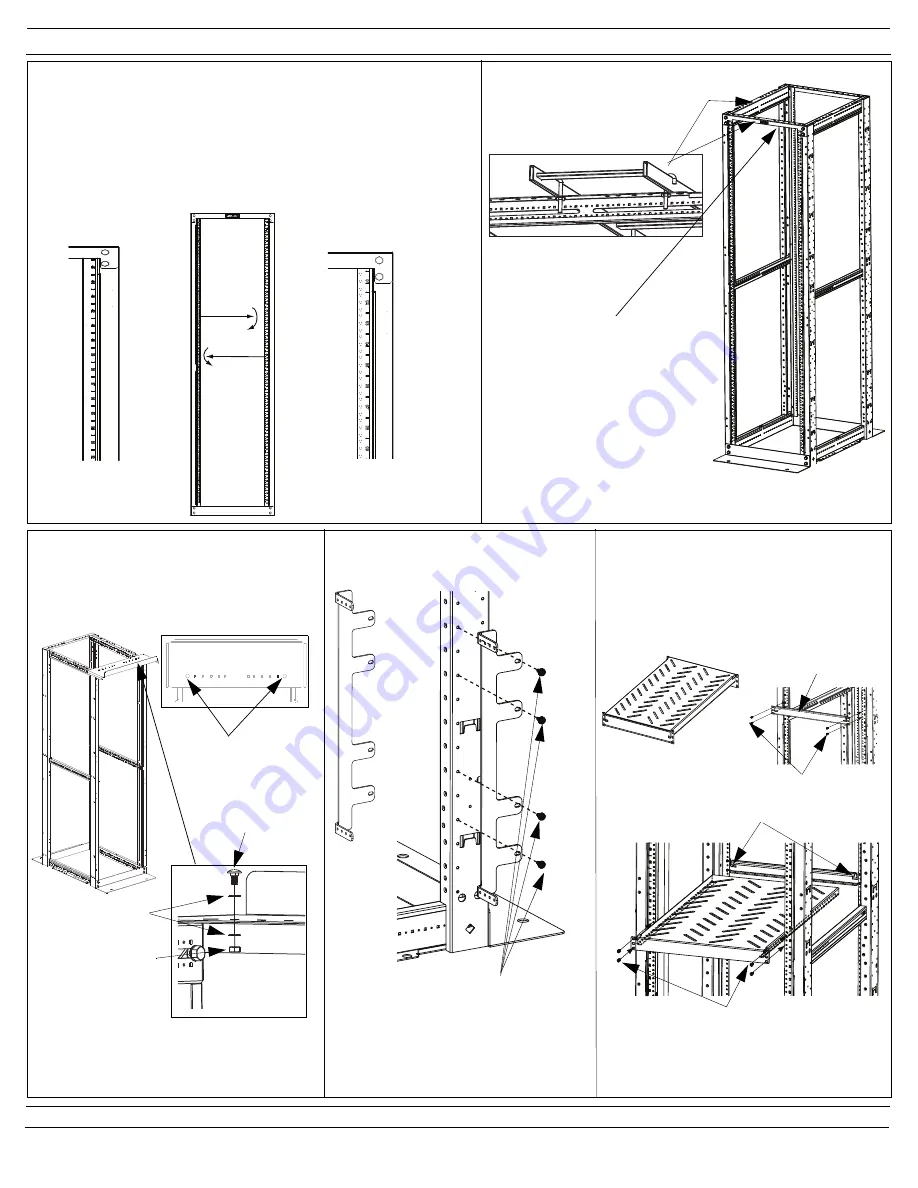
Flippable EIA Mounting Rails
The rack is shipped with rails in a numbers-up orientation. The rails can
be flipped to read in a numbers-down orientation by moving 1 right rail and
1 left rail in tandem. Remove (3) 5/16"-18 X 3/4" Mounting Bolts on each
rail. Then flip
right
rail so that numbering reads down and bolt to
left
side
of assembly using bolt orientation shown. Then flip
left
rail so that num-
bering reads down and bolt to
right
side of assembly using bolt orienta-
tion shown.
Numbering-Up
Orientation
Numbering-Down
Orientation
Use J-Bolt mounting holes for
securing ladder rack to the 4-post
rack.
R4PWF
Apply Antioxidant Paste to painted surfaces that
the 3/8" paint piercing washers will come in con-
tact with.
Mounting Locations
Fig, 1
CVPPB-
Zero RU Bracket- to mount 1RU
EIA 19" copper and fiber patch panels to the
side of rack posts.
CVPPB
Secure to desired hole location
using #12-24 screws
Side of post installation
RSHLF-
Shelf for 30" Deep rack
RSHLF23-
Shelf for 23" Deep rack
RSHLF36-
Shelf for 36" Deep rack
Mount bracket to
desired RU in rear of
rack
Slide shelf into slots in rear mounting bracket
Secure with (4) #12-24 screws
#12-24 screws
Shelf
Secure the waterfall as shown in Fig. 1 using
provided hardware.
(2) 1/4-20 bolts
(4) Paint
piercing washers
(2) 1/4-20 nuts
Note:
Shelf load rating is 275 lbs. when rails are
spaced a minimum of half the shelf depth.
Note:
Shelf is designed to support large net-
working equipment in combination with sup-
plied equipment mounting flanges.
J-Bolts up to 3/8" in diameter may
also be installed directly to the top
angle without interference with the
top mounting RU space.


