SMARTZONE UPS USER MANUAL
28
Relay Card (URC005)
The intelligent slot on the UPS unit may accept either the Relay card or the Network
card, not both. The Relay card is not supported in the 3-phase UPS units since these
units have built-in dry contact points. Follow the steps in the
section to install or remove the Relay card from the UPS unit.
CAUTION
! DO NOT TOUCH THE RELAY CARD WITHOUT PROPER ESD
PROTECTION.
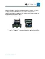
The 12-pin relay card allows the user to monitor specific status on the UPS. The
predefined monitoring contact points on the relay card change state when the status in
the UPS changes state.
Terminal
NO.
Terminal
function
Description
1
Common
source
common point for all contacts on the relay card
2
UPS ON =
Open
When the UPS is switched ON, Pin 1 to Pin 2 would
change from NC (Normal Closed) to Open.
3
AC fail =
Open
When the input utility power fails, Pin 1 to Pin 3 would
change from NC (Normal Closed) to Open.
4
AC fail =
Close
When the input utility power fails, Pin 1 to Pin 4 would
change from NO (Normal Opened) to Close.
5
Batt low =
Open
When the battery voltage is low, Pin 1 to Pin 5 would
change from NC (Normal Closed) to Open.
6
Batt low =
Close
When the battery voltage is low, Pin 1 to Pin 6 would
change from NO (Normal Opened) to Close.
7
UPS alarm =
Open
When the UPS has an alarm, Pin 1 to Pin 7 would change
from NC (Normal Closed) to Open.
8
UPS alarm =
Close
When the UPS has an alarm, Pin 1 to Pin 8 would change
from NO (Normal Opened) to close.
9
Bypass
active =
Open
When the UPS is working in the Bypass state, Pin 1 to Pin
9 would change from NC (Normal Closed) to Open.
10
Bypass
active =
Close
When the UPS is working in the Bypass state, Pin 1 to Pin
10 would change from NO (Normal Opened) to Close.
11
UPS fault =
Open
When the UPS has a fault, Pin 1 to Pin 11 would change
from NC (Normal Closed) to Open.
12
UPS fault =
Close
When the UPS has a fault, Pin 1 to Pin 12 would change
from NO (Normal Opened) to Close.

