SMARTZONE UPS USER MANUAL
113
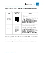
Appendix H: 10 to 20kVA REPO Port Definition
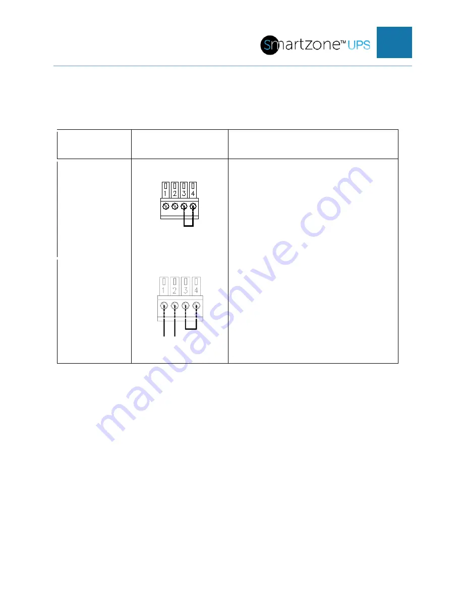
Connection diagram:
EPO
REPO Wiring
Diagram
Function
EPO-NC
(Default)
1. Remove the wire jumper between
terminals 3 & 4.
2. Connect wires from the Normally
Closed (NC) contacts (terminal 3 & 4)
of the NC EPO switch/relay.
The EPO function will be triggered when
the wire jumper between pins 3 and 4 is
removed or the EPO switch/relay
changes to an open state.
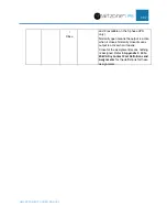
EPO-NO
1. Keep the wire jumper between
terminals 3 & 4.
2. Connect wires from the Normally
Open (NO) contacts (terminals 1 & 2)
of the NO EPO switch/relay.
The EPO function will be triggered when
wire jumper between terminals 3 and 4 is
removed or the EPO switch/relay
connected between pins 1&2 contacts
changes to a closed state.
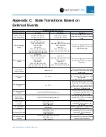
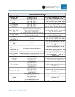
Connection between the remote EPO dry contact and UPS REPO port per the desired
configuration above.
A remote emergency stop dry contact may be installed in a remote location and
connected with simple wires to the REPO port per the desired configuration above.

