PVIQ™ CONNECTIVITY SYSTEM USER MANUAL V 1.0
123
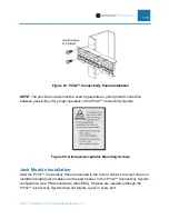
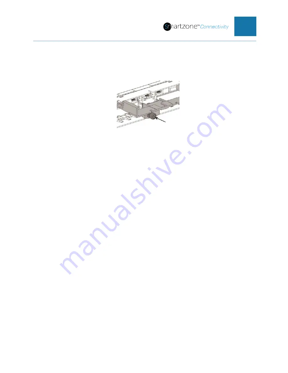
4. Secure the bracket to the patch panel using a Phillips-head screwdriver to push
in and turn the securing screw.
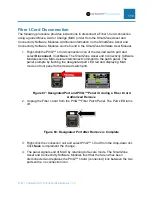
Figure 103: Mounting Bracket, step 4
Installing the Intelligent Modules
With the mounting brackets securely in place, the next step is to install the Intelligent
Modules:
•
Panel Manager (PM)
•
Expansion Module(s) (EMs)
The installation procedure is the same for both the PM and the EM. However, the PM
must be installed in the patch panel or fiber tray containing the Panel Manager Interface
Unit. The PM Interface Unit can be identified by the Provisioning Port – the RJ45 jack
on the front of the unit.
NOTE: PViQ™ Connectivity panels must be shipped with the PM, EM, or Fiber Trays
uninstalled to prevent permanent damage.
Slide the PM or EM into the mounting bracket as shown below.


