background image


SMARTZONE  G6 IRUPS USER  MANUAL 


14 


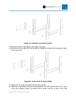
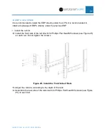
Figure 10: Install the Front Side of Rails 

3. Adjust  the rail size  according to the depth of the rack 
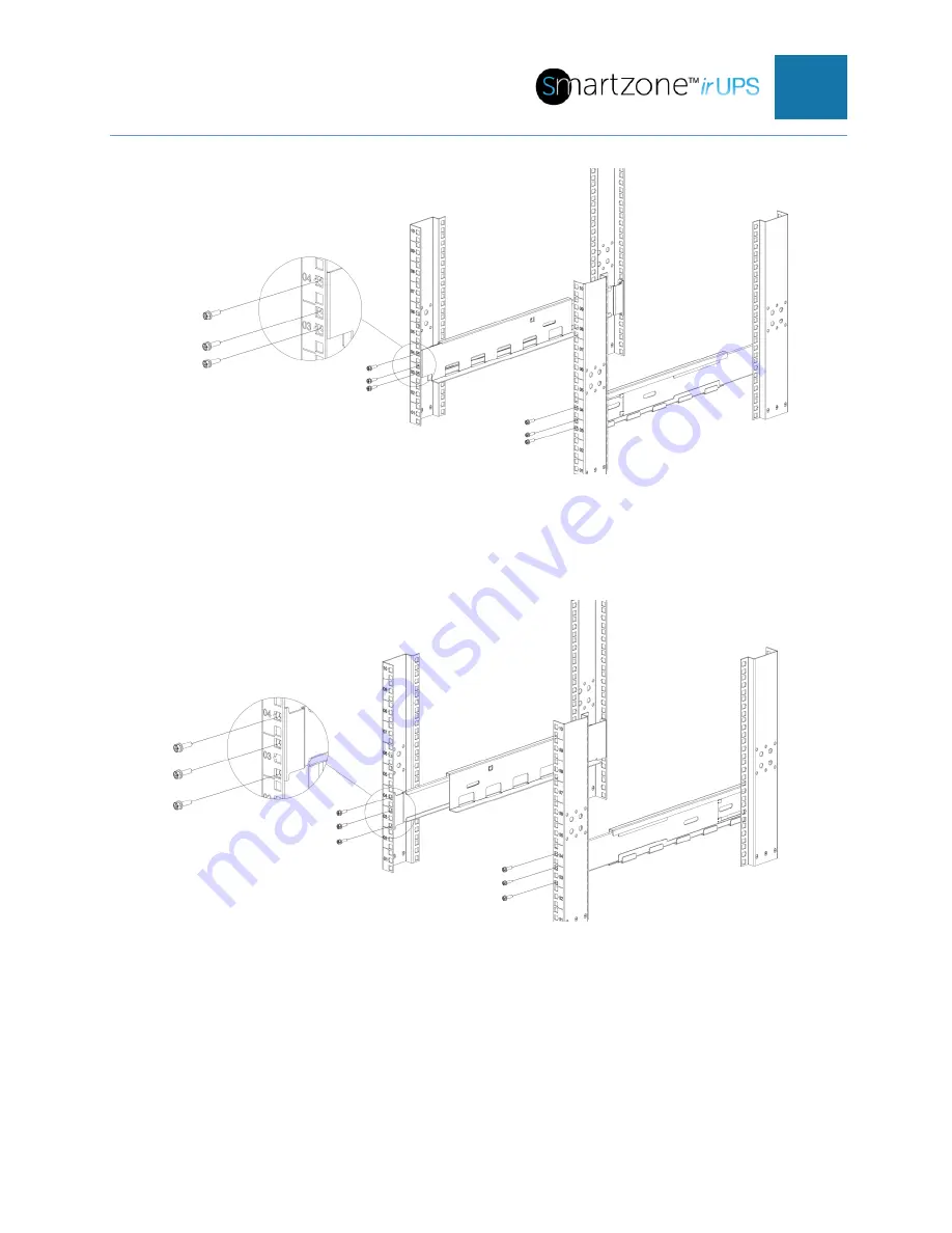
4. Assemble  the rear side of the rail kit with 3x Phillips  Pan Head M5 screws (see Figure 

11) on each rail. 


Figure 11: Install the Rear Side of Rails 

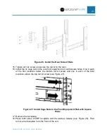
5. Tighten  all 12x screws to secure the rail  kit to the rack. 
6. Install  the 4x cage nuts in the rack front equipment  rail, with square  holes.  One in each 

of the first locations  below the bottom rail kit screw and one in each of the first locations 
above the top rail kit screw (see Figure  12). 

Summary of Contents for Smartzone U01N11V

Page 1: ...Installation Manual 1 20 kVA Uninterruptible Power Supply 1 20 kVA External Battery Pack Maintenance Bypass Switch Battery Cartridges ...

Page 2: ... Post Racks 8 2U UPS Units U01N11V U01S11V U01N12V U01S12V U01N13V U01S13V U02N11V U02S11V U02N12V U02S12V U03N11V U03S11V U03N12V U03S12V 8 2U EBP Units UVP024 UVP036 UVP048 UVP072 13 3U UPS Units U05N11V U05S11V U06N11V U06S11V U06N12V U06S12V U10N11V U10S11V U10N12V U10S12V U10N32V U10S32V U15N32V U15S32V U20N32V U20S32V 18 3U EBP Unit UVP240 22 3U MBS Unit UMB20K 28 4U EBP Unit UVP480 32 Two P...

Page 3: ...or Single Phase Output 43 Parallel Mode System Configuration with 3 Phase or Single Phase Output 48 Optional MBS for 3 Phase UPS 51 Section 5 Replacing Battery Cartridges 52 Internal Battery Cartridges in the 1 3kVA UPS Units UVC024 UVC036 UVC048 UVC072 52 EBP Battery Cartridge Sets for the 1 3kVA UPS Systems UVD024 UVD036 UVD048 UVD072 54 EBP Battery Cartridge Sets for the 5 10kVA UPS Systems UVD...

Page 4: ...SMARTZONE G6 IRUPS USER MANUAL 3 Appendix F What s Included 5 10kVA EBP UVP240 65 Appendix G What s Included 10 20kVA EBP UVP480 66 Appendix H What s Included Maintenance Bypass Switch UMB20K 67 ...

Page 5: ...t units The rail mounting kit is used for the preferred mounting in a four post rack The tower mounting kit is used for mounting on the floor or desk in a vertical orientation Refer to the appropriate Appendix in this manual for a detailed list of the components included with the product The following three sections provide the information on handling installing and wiring the chassis in this manu...

Page 6: ...l safety rules No liability is assumed for not following the safety rules Handling Instructions Before moving the UPS be sure to use the original packaging materials to prevent or reduce the possibility of personal injury or damage to the product Preparation 1 Condensation must be taken if the UPS system is moved directly from a cold to warm environment The UPS system must be free of any moisture ...

Page 7: ...ould be mounted in an environment where the temperature is within the required specs Temperature is a major factor in determining battery life and capacity In a normal installation the battery temperature is maintained between 15 C and 25 C Keep batteries away from heat sources or main air ventilation area etc 16 Units with internal battery cartridges and battery cartridges must be stored in an en...

Page 8: ...risk of electric shock The battery circuit is not isolated from the input voltage Hazardous voltages may exist between the battery terminals and the ground on the UPS Before touching please verify that no voltage is present 26 Batteries may cause electric shock and have a high short circuit current Take the precautionary measures specified below and any other measures necessary when working with t...

Page 9: ...unit should not use this mounting technique due to physical configuration and physical weight of the unit Four Post Racks The UPS EBP and MBS units comes with all the hardware required for installation in a standard EIA or JIS seismic rated four post rack with square or M5 threaded mounting holes The rail assemblies adjust to mount in 19 racks with a distance from front to rear from 460 1000 mm 18...

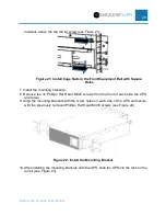
Page 10: ...x Phillips Pan Head M5 screws see Figure 2 on each rail Figure 2 Install the Rear Side of Rails 5 Tighten all 12x screws to secure the rail kit to the rack 6 Install the 4x cage nuts in the rack front equipment rail with square holes One in each of the first locations below the bottom rail kit screw and one in each of the first locations above the top rail kit screw see Figure 3 ...

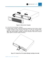
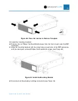
Page 11: ...ts in the Front Equipment Rail with Square Holes 7 Remove the faceplate 8 Press both sides of UPS faceplate until the latches release see Figure 4 Figure 4 Press the Latches to Remove Faceplate b Remove the faceplate see Figure 5 Figure 5 Remove the Faceplate ...

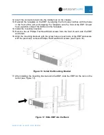
Page 12: ...e and snapping the faceplate onto the front of the UPS Should have a positive snap of the latches on the faceplate CAUTION A small amount of arcing may occur when connecting the internal battery cartridge This is normal and will not harm personnel Connect the cables quickly and firmly 12 Install the mounting brackets 13 Remove the 2x Phillips Flat Head M4x8 screws from the front of each side the U...

Page 13: ... installing the mounting brackets onto the UPS slide the UPS into the rack on the rail kit see Figure 8 Figure 8 Slide UPS into the Rack 16 Align the mounting brackets with the screw holes on the rack and secure the UPS with the supplied 4x Phillips Hex Head M5 screws see Figure 9 ...

Page 14: ...UVP048 UVP072 It is recommended to install the first EBP directly under the UPS It is recommended to install all subsequent EBPs directly under the previous EBP 1 Install the rail kit 2 Install the front side of the rail kit with 3x Phillips Pan Head M5 screws see Figure 10 on each rail Do not tighten the screws ...

Page 15: ... Phillips Pan Head M5 screws see Figure 11 on each rail Figure 11 Install the Rear Side of Rails 5 Tighten all 12x screws to secure the rail kit to the rack 6 Install the 4x cage nuts in the rack front equipment rail with square holes One in each of the first locations below the bottom rail kit screw and one in each of the first locations above the top rail kit screw see Figure 12 ...

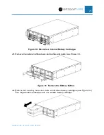
Page 16: ...Square Holes 7 Remove the faceplate 8 Press both sides of EBP faceplate until the latches release and remove see Figure 13 Figure 13 Press the Latches and Remove Faceplate 9 Loosen the outer screws on the battery covers move the battery cover to the center then pull the outside out see Figure 14 ...

Page 17: ... in the chassis connect a battery cartridge to each connector see Figure 15 Press the connector tightly together to ensure a proper connection Connect the other battery cartridge in the EBP Both internal battery cartridges should be connected Press each connector tightly together to ensure a proper connection Figure 15 Connect the First Internal Battery Cartridge Connector ...

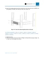
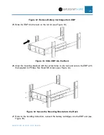
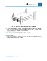
Page 18: ...he latches on the faceplate 14 Install the mounting brackets 15 Remove the 2x Phillips Flat Head M4x8 screws from the front of each side the EBP and retain 16 Align the mounting brackets with the screw holes on each side of the EBP and secure with the previously removed Phillips Flat Head M4 8 screws see Figure 16 Figure 16 Install the Mounting Bracket 17 After installing the mounting brackets ont...

Page 19: ...rews see Figure 18 Figure 18 Secure the Mounting Brackets to the Rack 3U UPS Units U05N11V U05S11V U06N11V U06S11V U06N12V U06S12V U10N11V U10S11V U10N12V U10S12V U10N32V U10S32V U15N32V U15S32V U20N32V U20S32V 1 Install the rail kit 2 Install the front side of the rail kit with 3x Phillips Pan Head M5 screws see Figure 19 on each rail Do not tighten the screws ...

Page 20: ...ide of the rail kit with 3x Phillips Pan Head M5 screws see Figure 20 on each rail Figure 20 Install the Rear Side of Rails 5 Tighten all 12x screws to secure the rail kit to the rack 6 Install the 4x cage nuts in the rack front equipment rail with square holes One in each of the first locations below the bottom rail kit screw and one in each of the third ...

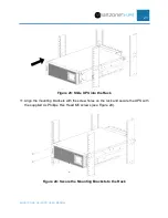
Page 21: ...ove the 4x Phillips Flat Head M4x8 screws from the front of each side the UPS and retain 9 Align the mounting brackets with the screw holes on each side of the UPS and secure with the previously removed Phillips Flat Head M4 8 screws see Figure 22 Figure 22 Install the Mounting Bracket 10 After installing the mounting brackets onto the UPS slide the UPS into the rack on the rail kit see Figure 23 ...

Page 22: ...21 Figure 23 Slide UPS into the Rack 11 Align the mounting brackets with the screw holes on the rack and secure the UPS with the supplied 4x Phillips Hex Head M5 screws see Figure 24 Figure 24 Secure the Mounting Brackets to the Rack ...

Page 23: ... the previous EBP 1 Install the rail kit 12 Install the front side of the rail kit with 3x Phillips Pan Head M5 screws see Figure 25 on each rail Do not tighten the screws Figure 25 Install the Front Side of Rails 13 Adjust the rail size according to the depth of the rack 14 Assemble the rear side of the rail kit with 3x Phillips Pan Head M5 screws see Figure 26 on each rail ...

Page 24: ...l with square holes One in each of the first locations below the bottom rail kit screw and one in each of the third locations above the top rail kit screw see Figure 27 Figure 27 Install Cage Nuts in the Front Equipment Rail with Square Holes 17 Remove the faceplate 18 Press both sides of EBP faceplate until the latches release see Figure 28 Then remove the faceplate form the front of the unit ...

Page 25: ...ips Flat Head M4x8 screws from the front of each side the EBP and retain 21 Align the mounting brackets with the screw holes on each side of the EBP and secure with the previously removed Phillips Flat Head M4 8 screws see Figure 29 Figure 29 Install the Mounting Bracket 22 Disconnect all three battery cartridge connectors see Figure 30 ...

Page 26: ...Cartridges 23 Remove the battery baffle screws and baffles and retain see Figure 31 Figure 31 Remove the Battery Baffles 24 Refer to the handling instruction take out all three battery cartridges see Figure 32 Two larger battery cartridges and one smaller battery cartridge ...

Page 27: ...e 33 Figure 33 Slide EBP into the Rack 26 Align the mounting brackets with the screw holes on the rack and secure the EBP with the supplied 4x Phillips Hex Head M5 screws see Figure 34 Figure 34 Secure the Mounting Brackets to the Rack 27 Refer to the handling instruction reinsert the battery cartridges into the EBP unit see Figure 35 ...

Page 28: ...ry Cartridges into the EBP Unit 28 Reinstall the battery baffles the screws see Figure 36 Figure 36 Reinstall Battery Baffles and Screws 29 Reconnect the Battery Cartridge connectors see Figure 37 Press each connector tightly together to ensure a proper connection ...

Page 29: ...les in the front of the unit and snapping the faceplate onto the front of the EBP Should have a positive snap of the latches on the faceplate 3U MBS Unit UMB20K It is recommended to install the MBS directly above the UPS 1 Install the rail kit 31 Install the front side of the rail kit with 3x Phillips Pan Head M5 screws see Figure 38 on each rail Do not tighten the screws ...

Page 30: ...ide of the rail kit with 3x Phillips Pan Head M5 screws see Figure 39 on each rail Figure 39 Install the Rear Side of Rails 34 Tighten all 12x screws to secure the rail kit to the rack 35 Install the 4x cage nuts in the rack front equipment rail with square holes One in each of the first locations below the bottom rail kit screw and one in each of the third ...

Page 31: ...ve the 2x Phillips Flat Head M4x8 screws from the front of each side the MBS and retain 38 Align the mounting brackets with the screw holes on each side of the MBS and secure with the previously removed Phillips Flat Head M4 8 screws see Figure 41 Figure 41 Install the Mounting Bracket MBS 39 After installing the mounting brackets onto the MBS slide the MBS into the rack on the rail kit see Figure...

Page 32: ...igure 42 Slide MBS into the Rack MBS 40 Align the mounting brackets with the screw holes on the rack and secure the MBS with the supplied 4x Phillips Hex Head M5 screws see Figure 43 Figure 43 Secure the Mounting Brackets to the Rack MBS ...

Page 33: ...e previous EBP 1 Install the rail kit 41 Install the front side of the rail kit with 2x Phillips Pan Head M5X12 screws see Figure 44 on each rail Do not tighten the screws Figure 44 Install the Front Side of Rails 42 Adjust the rail size according to the depth of the rack 43 Assemble the rear side of the rail kit with 2x Phillips Pan Head M5X12 screws see Figure 45 on each rail ...

Page 34: ... to secure the rail kit to the rack 45 Remove the faceplate 46 Press both sides of EBP faceplate until the latches release see Figure 46 Then remove the faceplate form the front of the unit Figure 46 Press the Latches to Remove Faceplate 47 Remove the screws and battery baffle from EBP see Figure 46 ...

Page 35: ...34 Figure 46 Remove Battery Baffle on the EBP 48 Refer to the handling instruction remove all battery cartridges see Figure 47 Figure 47 Remove Battery Cartridges from EBP 49 Slide the EBP into the rack on the rail kit see Figure 48 ...

Page 36: ... EBP with the supplied 4x Phillips Hex Head M5 screws see Figure 49 Figure 49 Secure the Mounting Brackets to the Rack 51 Refer to the handling instruction reinsert all four battery cartridges into the EBP see Figure 50 Figure 50 Reinsert the Battery Cartridges into the EBP 52 Install and secure the screws on the battery baffles see Figure 51 ...

Page 37: ... specification on the Panduit website for the appropriate shelf to uses with each unit Note The unit is not secured to the rack in this technique it is just set on the shelf CAUTION The units are heavy Removing the units from its carton requires a minimum of two people The 3 phase EBP UVP480 cannot be mounted in a two post rack there is no shelf to support the weight of this unit The weight of thi...

Page 38: ...the EBP s directly next to the UPS so that all wiring between the units can use the wiring provided with the units NOTE Tower mounting stands are required for each individual unit 2U Units U01N11V U01S11V U01N12V U01S12V U01N13V U01S13V U02N11V U02S11V U02N12V U02S12V U03N11V U03S11V U03N12V U03S12V UVP024 UVP036 UVP048 UVP072 1 Assemble the tower kit see Figure 52 Figure 52 Tower Kit for 2U Units...

Page 39: ... the hole in the faceplate and snapping the faceplate onto the front of the UPS Should have a positive snap of the latches on the faceplate se Figure 54 b Install the faceplate on the EBP by aligning the front panel latches with the holes in the front of the unit and snapping the faceplate onto the front of the EBP Should have a positive snap of the latches on the faceplate ...

Page 40: ... one extender in each support see Figure 455 Figure 55 Tower Kit for 3U Units 2 Place the unit into the tower kit for UPS and EBP units neither the LCD panel nor Battery Pack signage rotates 3 Install the faceplate on the unit by aligning the front panel latches with the holes in the front of the unit and snapping the faceplate onto the front of the unit Should have a positive snap of the latches ...

Page 41: ...eplate onto the Front of the UPS 3 Phase Units U10N32V U10S32V U15N32V U15S32V U20N32V U20S32V UVP480 UMB20K The UVP480 cannot be tower mounted due to physical constrains Since this is the battery for all 3 phase unit it is not recommended to tower mount any 3 phase units ...

Page 42: ...V U10S11V U10N12V U10S12V 57 For units with an input power plug properly insert the plug into the region s standard outlet NOTE Each part of the system must maintain a connected earth ground 58 For units with a hardwire input ensure that there is no power to the wires use lock out tag out at the breaker panel The wire used for all three conductors should be 10mm2 This wire must conform to the loca...

Page 43: ...ng terminal onto each wire with a standard crimping tool for 10 mm2 wire 74 Connect each wire under the appropriate screw as indicated on the back of the UPS NOTE Each part of the system must maintain a connected earth ground 75 After completing the wiring confirm again that all wiring is correct 76 Replace the terminal block cover on the rear panel of the UPS 77 Then properly insert the plugs fro...

Page 44: ...ingle Phase Output All UPS units by default are configured as a single mode system A single mode system is a single UPS connected to an AC power source and that UPS provide the AC power to the load This section provides the electrical connections for Single UPS with a 3 Phase input and a 3 Phase or a Single Phase Output When selecting connecting and routing power cables follow local safety regulat...

Page 45: ...ng requirements are met 90 Routing mode Routing the cables over the cable ladder or bracket in a single layer IEC60364 5 52 middle E 91 The ambient temperature is 30 C 92 The AC voltage loss is less than 3 and the DC voltage loss is less than 1 93 90 C copper flexible cable 94 The length of the AC power cables are no longer than 30 m and DC power cables are no longer than 50 m 95 After completing ...

Page 46: ...3 3 380 400 415 VAC 380 400 415 VAC 26 9 A each phase 15 2 A each phase 40 A each phase not required 10 mm2 6 mm2 U15N32V Input Output 3 1 380 400 415 VAC 220 230 240 VAC 34 9 A each phase 68 2 A 100 A not required 25 mm2 16 mm2 Input Output 3 3 380 400 415 VAC 380 400 415 VAC 34 9 A each phase 22 8 A each phase 40 A each phase not required 10 mm2 6 mm2 U20N32V Input Output 3 1 380 400 415 VAC 220...

Page 47: ...380 400 415 VAC 34 9 A each phase 22 8 A each phase 40 A each phase Not required 40 A each phase not required 10 mm2 6 mm2 10 mm2 6 mm2 U20N32V Input Output 3 1 380 400 415 VAC 220 230 240 VAC 42 9 A each phase 90 9 A 50 A each phase Not required 125 A not required 16 mm2 25 mm2 35 mm2 25 mm2 Input Output 3 3 380 400 415 VAC 380 400 415 VAC 42 9 A each phase 30 4 A each phase 50 A each phase Not r...

Page 48: ...After completing the wiring confirm again that all wiring is correct 113 Close the terminal block cover on the rear panel of the UPS and secure it with the screws retained from an earlier step 114 Plug the other end of this cable into the back of the EBP Insert and press the connector tightly together to ensure a proper connection 115 For additional EBP units in the system connect with the battery...

Page 49: ...t All 3 phase UPS units may optionally be configured into a parallel mode system Figure 60 shows a high level power and control connection diagrams of the parallel UPS system A parallel mode system allows two to four UPS unit of the same SKU to be connected in parallel NOTE Initial release of the product only allows two UPS units to be connected in parallel The parallel mode allows the group of UP...

Page 50: ...hould be physically located near each other to minimize the load sharing effects due to environmental conditions Parallel Mode Wiring Following the power and control wiring as indicated in Figure 60 1 Connect the UPS Parallel System to the input source 117 Before wiring together make sure each UPS input breaker is in the off position and there is no output from each UPS unit 118 Connect the Mains ...

Page 51: ...ons and the input phase sequence is correctly connected 131 Confirm that the battery voltage of all EBP groups are correct 132 Confirm that the parallel control cables are connected in a ring configuration between all UPS units in the Parallel mode system control connection in Figure 60 133 Power ON the first UPS unit and set the working mode to Parallel set the Parallel ID to 1 set the number of ...

Page 52: ...Toggle the utility breaker ON and OFF to test all the UPS converter systems from the utility to battery and restore function are properly working 141 If all is properly working then the system may be powered up Optional MBS for 3 Phase UPS ...

Page 53: ...dges in a system at the same time with new battery cartridges of the same SKU for that unit UPS and EBP 1 Change to Bypass Mode this will not allow the UPS to transition to Battery Mode will the battery cartridges are being replaced 2 Remove the faceplate 142 Press both sides of UPS faceplate until the latches release see Figure 61 Figure 61 Press the Latches to Remove Faceplate 143 Remove the fac...

Page 54: ...t the Internal Battery Cartridge Connector 146 Loosen the outer screws on the battery covers move the battery cover to the center then pull the outside out see Figure 64 Figure 64 Remove Battery Cover 147 Slide the battery cartridge out of the UPS 148 Slide the new battery cartridge into the UPS 149 Replace the battery cover reverse order of above steps 4 1 150 Connect the new battery cartridge to...

Page 55: ...n a system at the same time with new battery cartridges of the same SKU for that unit UPS and EBP 1 Change to Bypass Mode this will not allow the UPS to transition to Battery Mode will the battery cartridges are being replaced 2 Remove the faceplate 153 Press both sides of EBP faceplate until the latches release and remove see Figure 65 Figure 65 Press the Latches and Remove Faceplate 154 Loosen t...

Page 56: ...n the chassis disconnect a battery cartridge from each connector see Figure 67 Press the connector tightly together to ensure a proper connection Connect the other battery cartridge in the EBP Both internal battery cartridges should be connected Press each connector tightly together to ensure a proper connection Figure 67 Disconnect the First Internal Battery Cartridge Connector ...

Page 57: ...S Systems UVD240 Replace battery cartridges with only the same SKU It is recommended to replace all battery cartridges in a system at the same time with new battery cartridges of the same SKU for that unit UPS and EBP 1 Change to Bypass Mode this will not allow the UPS to transition to Battery Mode will the battery cartridges are being replaced 163 Remove the faceplate 164 Press both sides of EBP ...

Page 58: ...artridges 166 Remove the battery baffle screws and baffles and retain see Figure 70 Figure 70 Remove the Battery Baffles 167 Refer to the handling instruction take out all three battery cartridges see Figure 71 Two larger battery cartridges and one smaller battery cartridge ...

Page 59: ...e Sets for the 10 20kVA 3 Phase UPS Systems UVD480 Replace battery cartridges with only the same SKU It is recommended to replace all battery cartridges in a system at the same time with new battery cartridges of the same SKU for that unit UPS and EBP 1 Change to Bypass Mode this will not allow the UPS to transition to Battery Mode will the battery cartridges are being replaced 2 Remove the facepl...

Page 60: ...ove Battery Cartridges from EBP 173 Refer to the handling instruction slide the new battery cartridges into the EBP unit 174 Reinstall the battery baffles the screws reverse order of above steps 4 1 175 Connect the new battery cartridges to the EBP Press each connector tightly together to ensure a proper connection 176 Replace the UPS faceplate 177 Change to Normal Mode ...

Page 61: ...SMARTZONE G6 IRUPS USER MANUAL 60 Appendix A What s Included 1 3kVA NA UPS U01N11V U01S11V U01N13V U01S13V U02N11V U02S11V U03N11V U03S11V ...

Page 62: ...de 1 Booklet 5 DB9 to DB9 RS232 1 5M Serial Cable 1 piece 6 USB 1 to USB B 1 2M Serial Cable 1 piece 7 Internal Battery Cartridge Installed UVC036 UVC048 or UVC072 depending on UPS SKU 1 cartridge 8 Schuko CEE7 EU1 16P to C14 or C20 Input Power Cord depending on UPS SKU 1 piece 9 BS1363A to C14 Input Power Cord 1 piece 10 Rack Rail Mounting Kit URMKIT1 1 kit N versions only 11 Intelligent Network ...

Page 63: ...SMARTZONE G6 IRUPS USER MANUAL 62 Appendix C What s Included 1 3kVA EBP UVP024 UVP036 UVP048 UVP072 ...

Page 64: ...SMARTZONE G6 IRUPS USER MANUAL 63 Appendix D What s Included 5 10kVA UPS U05N11V U05S11V U06N11V U06S11V U06N12V U06S12V U10N11V U10S11V U10N12V U10S12V ...

Page 65: ...SMARTZONE G6 IRUPS USER MANUAL 64 Appendix E What s Included 10 20kVA UPS U10N32V U10S32V U15N32V U15S32V U20N32V U20S32V ...

Page 66: ...SMARTZONE G6 IRUPS USER MANUAL 65 Appendix F What s Included 5 10kVA EBP UVP240 ...

Page 67: ...SMARTZONE G6 IRUPS USER MANUAL 66 Appendix G What s Included 10 20kVA EBP UVP480 ...

Page 68: ...SMARTZONE G6 IRUPS USER MANUAL 67 Appendix H What s Included Maintenance Bypass Switch UMB20K ...

Reviews: