SMARTZONE G6 UPS USER MANUAL
91
Appendix F: 10 to 20kVA REPO port definition
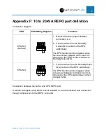
Connection diagram:
EPO
EPO Wiring Diagram
Function
EPO-NC
(Default)
1. Remove the wire jumper between
terminals 3 & 4.
2. Connect wires from the Normally
Closed (NC) contact of the EPO
switch/relay.
The EPO function will be triggered when
the wire jumper between pins 3 and 4 is
removed or the EPO contact changes to
Normally Open (NO).
EPO-NO
1. Connect wires from the Normally Open
(NO) contact of the EPO switch/relay.
The EPO function will be triggered when
wire jumper between terminals 3 and 4 is
removed or the EPO switch/relay contact
changes to NC.
Connection between the button and UPS REPO port.
A remote emergency stop switch can be installed in a remote location and connection
through simple wires to the REPO connector.


