background image

WSN Gateway Hardware Installation Manual

-

10

-

l

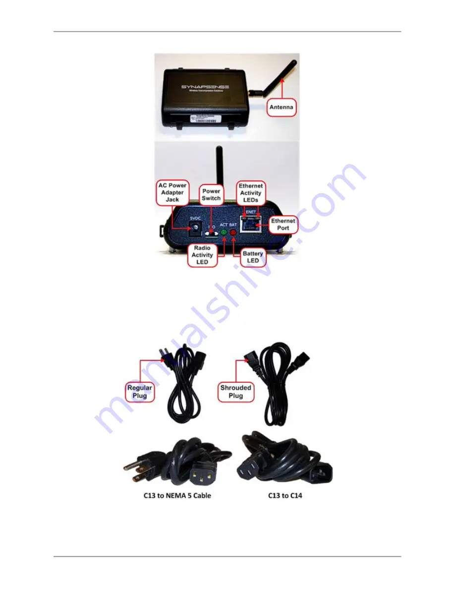
AC Power Adapter and Cords:

o

C13 to C14 power cord (shroud plug) for use in rack outlets

o

C13 to NEMA cable (5-15) power cord for use in non-rack outlets (NEMA 5-
15)

l

Gateway Mounting Shelf (Optional)

Summary of Contents for Synapsense WSN

Page 1: ...Release 6 8 Issue 2 WSN Gateway Hardware Installation Manual...

Page 2: ...ical photocopying recording or otherwise without written permission from Panduit No patent liability is assumed with respect to the use of the information contained herein Although every precaution ha...

Page 3: ...e 12 Software 12 Tools and Materials 12 Installation Procedures 13 General Installation Guidelines 13 Installation Preparations 14 WSN Gateway Installation 14 Configure WSN Gateways 15 Mount WSN Gatew...

Page 4: ...des the scope overview applic ation and block diagrams and kit components con tent for installing and configuring Gateways in data centers Requirements This chapter lists the hardware software tools a...

Page 5: ...iangular yellow electrical icon denotes a safety warning of a physical or elec trical nature Document References The documents listed in this section affect the activities in this document Refer to th...

Page 6: ...y into high noise areas When performing subfloor work in a data center be careful not to stress crush pull or disconnect wiring and hoses running underneath electrical and data cables leak detectors e...

Page 7: ...WSN Gateway Hardware Installation Manual 7 Severity 3 4 Issues Email normal business hours systemsupport panduit com...

Page 8: ...erences section for document list This document applies only to the installation and configuration of Gateway devices Overview The Gateway is a wireless to Ethernet transceiver that collects data from...

Page 9: ...WSN Gateway Hardware Installation Manual 9 Kit Components Typically a WSN Gateway kit contains l One wireless WSN Gateway device with pre attached antenna...

Page 10: ...Installation Manual 10 l AC Power Adapter and Cords o C13 to C14 power cord shroud plug for use in rack outlets o C13 to NEMA cable 5 15 power cord for use in non rack outlets NEMA 5 15 l Gateway Mou...

Page 11: ...WSN Gateway Hardware Installation Manual 11 l 3M Command Strips l Adhesive Cable Clips...

Page 12: ...data center including areas inside the subfloor and overhead plenums l Ladder or step stool sufficient to reach all WSN Gateway installation locations typ ically placed well above the height of all se...

Page 13: ...smooth surfaces such as the tops of server cabinets l Use adhesive cable clips to keep cable and AC Power Adapter wires neat and con tained l Each WSN Gateway installation location should have a 110...

Page 14: ...ic IP Verify the data center operators provided one static IP address per WSN Gateway Verify Ethernet Connection Verify the data center operators provided one Ethernet cable connection per WSN Gateway...

Page 15: ...y Steps Connect WSN Gateway to Laptop 1 With the WSN Gateway s Power Switch set to OFF connect the AC Power Adapter and Cord to the WSN Gateway 2 Plug Power Cord into an electrical outlet 3 Connect th...

Page 16: ...8 Write down the laptop s existing Host IP Address so it can be restored later Change IP Address field network address of the laptop to an IP address in the same subnet as the WSN Gateway to be config...

Page 17: ...Steps Addresses Subnet Masks default IP address sticker 192 168 0 2 on the bottom of the device 2 Log in as admin with the password PASS upper case Click OK to access the Remote Gateway Manager The R...

Page 18: ...Configuration link The Network Interface Configuration screen displays 5 Enter the IP address and Subnet Mask information in the IP Address field in CIDR form refer to Appendix B 6 If the customer pro...

Page 19: ...ice 2 Plug the Ethernet Cable into the next WSN Gateway device to be configured 3 Repeat the activities in this table for each WSN Gateway device to be installed in the data center 4 Once all WSN Gate...

Page 20: ...surface with alcohol wipes Allow area to dry thor oughly 2 Attach two Command Strips double sided adhesive strips to the back of the WSN Gateway 3 Connect the A C Power Adapter to the WSN Gateway and...

Page 21: ...e top of server cabinet Press firmly for 30 seconds 8 Secure and route AC Power Adapter wire and Ethernet Cable using adhesive Cable Clips 9 Repeat previous steps for remaining WSN Gateways to be ins...

Page 22: ...stomer 1 Using the Gateway Mounting Shelf mounting holes as a template position the shelf in the desired location i e wall or pillar and mark the holes to be drilled with a pencil 2 Using a drill and...

Page 23: ...ted power outlet 6 Connect the designated Ethernet Cable originating from a server port assigned by the data center s IT department to the WSN Gate way 7 Turn the Power Switch to ON l The Radio Activi...

Page 24: ...ivity Steps 8 Insert the WSN Gateway s mounting spacers in the shelf s front mounting holes and slide the WSN Gateway downward to bottom of mounting hole slots 9 Secure and route AC Power Adapter wire...

Page 25: ...ed to the Final Install ation Activities section Final Installation Activities Perform the activities in Table 6 to complete the activities for the WSN Gateway install ation Table 6 Final Installation...

Page 26: ...installed in areas in which there is a clear line of sight for wireless sensor s radio transmissions 3 Verify Ethernet cables and AC Power Adapter wires are secured where needed Inspect Software Comm...

Page 27: ...over a WSN Gateway device on the display The name and status of the device displays next the WSN Gateway graphic representation NOTE In a data center with multiple WSN Gateway devices one WSN Gateway...

Page 28: ...ates Master not sync or Slave not sync the WSN Gateway is not communicating with the software Refer to Appendix B for tips on resolving con nectivity and communication issues 7 When issues are resolve...

Page 29: ...yed as the WSN Gateway powers on and joins a wireless network Table 7 WSN Gateway LED Lights Activity LED Response WSN Gateway device powered on The ACT radio activity and BAT battery LED lights illu...

Page 30: ...r in dot notation for example 255 255 255 0 It is now in slash notation for example 24 The chart below shows both types of notation The CIDR Prefix is the new way the Subnet Mask is represented in the...

Page 31: ...0 0 0 5 134 217 728 134 217 726 1 048 576 240 0 0 0 4 268 435 456 268 435 454 2 097 152 224 0 0 0 3 536 870 912 536 870 910 4 194 304 192 0 0 0 2 1 073 741 824 1 073 741 822 8 388 608 128 0 0 0 1 2 1...

Page 32: ...n WSN Gateway are off Yes Check power to the WSN Gateway ACT LED should be blinking BAT LED blinking Yes WSN Gateway is not receiving power running on batteries Ethernet port will not operate while on...

Page 33: ...nection res ult in invalid data Yes WSN Gateway may be in Diagnostic Mode See next test Is the WSN Gateway radio in Dia gnostic Mode Both LEDs are flash ing Yes Turn the WSN Gateway Power Switch to OF...

Reviews: