background image


TDP43ME 


PA26305A01 

Rev. 05  12-2011 

© Panduit Corp. 2011 


NOTE: In the interest of higher quality and value, Panduit products 
are continually being improved and updated.  Consequently, 
pictures may vary from the enclosed product.  


Website:  www.panduit.com 

Email: 

id-support@panduit.com


EU Website: 

www.panduit.com/emea 


EU Email:  

emeatoolservicecenter 

@panduit.com


Technical Support: 

Panduit Corp. • ID Products Division 

Cumming, GA 

Tel:  800-777-3300  

•  Fax: 708-532-1811   


Panduit Europe •  EMEA Service Center 

Almelo, Netherlands 

Tel: +31-546-580-

452  •  Fax: +31-546-580-441 


Panduit Europe • West World Headquarters 

Westgate, London 

England Tel: 208-601-

7200  •  Fax: 208-601-7319 


Summary of Contents for TDP43ME

Page 1: ...ct Website www panduit com Email id support panduit com EU Website www panduit com emea EU Email emeatoolservicecenter panduit com Technical Support Panduit Corp ID Products Division Cumming GA Tel 800 777 3300 Fax 708 532 1811 Panduit Europe EMEA Service Center Almelo Netherlands Tel 31 546 580 452 Fax 31 546 580 441 Panduit Europe West World Headquarters Westgate London England Tel 208 601 7200 ...

Page 2: ... to correct the interference at own expense EMS AND EMI COMPLIANCE STATEMENT FOR EUROPEAN USERS This equipment has been tested and passed with the requirements relating to electromagnetic compatibility based on the standards EN 55022 1998 A1 2000 A2 2003 CISPR 22 Class A EN 55024 1998 A1 2001 A2 2003 IEC 61000 4 Series EN 61000 3 2 2000 EN 61000 3 3 1995 The equipment also tested and passed in acc...

Page 3: ... the power outlet please check the voltage of the power source Disconnect the equipment from the voltage of the power source to prevent possible transient over voltage damage Don t pour any liquid to the equipment to avoid electrical shock CAUTION Keep the equipment away from moisture and humidity CAUTION ONLY qualified service personnel for safety reasons should open equipment Don t repair or adj...

Page 4: ...t Using Windows Updates XP 18 If The Printer Is To Be Installed On A USB Port Using Product CD 20 If The Printer Is To Be Installed On A Parallel Or Serial Port 23 If The Printer Is To Be Installed On An Ethernet Port 26 Installing An Ethernet Port For The TDP43ME Printer Win7 27 Installing An Ethernet Port For The TDP43ME Printer XP 41 3 CONTROL PANEL 53 3 1 LED Status 53 3 2 FEED Key 54 3 3 Self...

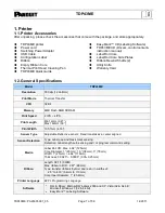
Page 5: ...Thermal Transfer CPU 32 Bit Memory 4MB Flash 8MB SDRAM Print Speed 2 IPS 4 IPS Print Length Min 12mm 0 47 Max 762mm 30 Print Width 105 7mm 4 16 Sensor Type Adjustable Reflective sensor Fixed transmissive center aligned Sensor Detection Type Label gap and black mark sensing Detection Label length auto sensing and or program command setting Media Label Roll OD Max 4 92 125mm Core Diameter 1 25mm 1 5...

Page 6: ...l Code RPS 128 PDF417 Datamatrix code QR code Interfaces Serial port RS 232 Baud rate 4800 115200 Xon Xoff DSR DTR USB port V2 0 Parallel port Bi direction Ethernet TCP IP Port wireless optional Control Panel Two Bi color LED Ready Status Function Key FEED Power Auto Switching 100 240VAC 50 60 Hz Environment Operation 41 F to 104 F 5 C to 40 C Storage 4 F to 122 F 20 C to 50 C Humidity Operation 3...

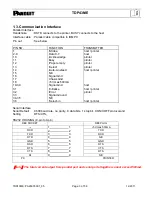
Page 7: ...d N C Signal Gnd Chasis Gnd 5V max 500mA Signal Gnd Initialize Error Signal Ground N C Select in host printer host printer printer printer printer host printer host host printer printer host printer Serial Interface Serial Default Setting 9600 baud rate no parity 8 data bits 1 stop bit XON XOFF protocol and RTS CTS RS232 HOUSING 9 pin to 9 pin DB9 SOCKET DB9 PLUG 1 1 5V max 500mA RXD 2 2 TXD TXD 3...

Page 8: ... VBUS D D GND Internal Interface UART1 wafer Ethernet module N C 1 1 N C TXD 2 2 RXD RXD 3 3 TXD CTS 4 4 RTS GND 5 5 GND RTS 6 6 CTS E_MD 7 7 E_MD RTS 8 8 CTS E_RST 9 9 E_RST 5V 10 10 5V GND 11 11 GND 5V 12 12 5V UART2 wafer Expansion module 5V 1 1 5V CTS 2 2 RTS TXD 3 3 RXD RTS 4 4 CTS RXD 5 5 TXD GND 6 6 GND ...

Page 9: ...arts 1 Cover Open Button 2 Top Cover 3 Label Roll Core 4 Ribbon Rewind Wheel 5 Print Mechanism 6 Ribbon Rewind Shaft Empty Ribbon Roll 7 Locking Tenon left right 8 Front Cover Piece 1 LED Light Ready 2 LED Light Status 3 FEED Key 4 CF Card Slot Cover 2 1 3 4 5 6 7 8 ...

Page 10: ...abel Slot 2 Power Switch 3 Ethernet Socket 4 USB Port 5 Parallel Port 6 Serial Port 7 AC Adaptor Socket 8 Wireless Port Antenna optional 2 Printer Installation This printer model has the following print modes Thermal Transfer TT When printing ribbon must be installed to transfer the print contents onto the media 1 2 5 4 6 7 3 8 ...

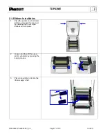
Page 11: ...Installation 1 Place the printer on a horizontal surface and open the top cover by pressing the Cover Open Buttons on both sides 2 Loosen and then lift the upper print mechanism by pressing the locking tenons 3 Place a new ribbon roll onto the ribbon supply shaft ...

Page 12: ...5 Wrap the ribbon around the Ribbon Shaft and stick the ribbon onto the Empty Ribbon Roll Core Note The Ribbon Core must not spin freely on Ribbon Shaft Mandrel Note Ribbon must be coated side out away from print head contact 6 Firmly close the upper print mechanism pressing down firmly on both sides of print mechanism ...

Page 13: ...p cover by pressing the Cover Open Buttons on both sides 2 Place the label roll onto the Label Roll Core 3 Loosen and lift the upper print mechanism by pressing the locking tenons 4 Feed the label through the two Label Guides to the Tear off Bar 5 Align the label guides to the label edge ...

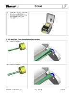
Page 14: ...9 12 2011 6 Close the upper print mechanism from the top to finish label installation pressing down firmly on both sides of the printer mechanism 2 3 Label Roll Core Installation Instruction A 1 roll core installation B 3 roll core installation ...

Page 15: ...er is powered off 2 Plug the power cable into the power adapter then connect the power adapter end to the printer power socket and the power cable into the power source outlet 3 Connect the USB cable to the USB port on the printer and on the PC 4 Power on the printer and the printers LED will light ...

Page 16: ... is attached to the USB port when the printer is turned ON the following window will appear The installation will most likely proceed without interruption If you click on the balloon for Check here for status the window at the left will pop up This indicates that all processes are complete and the printer has been correctly installed The printer is now ready for use ...

Page 17: ...o TDP43ME driver was found Click CLOSE Go to the WINDOWS orb in the bottom left corner and click Go to DEVICES and PRINTERS and click The window at the left will pop up If the printer appears in the PRINTERS and FAXES line then it is installed correctly If it appears in the UNSPECIFIED line then there is an issue most likely an incorrect or a missing driver Right click on the printer in the UNSPEC...

Page 18: ...9 12 2011 This window will pop up Click on HARDWARE tab This window will pop up Highlight PANDUIT TDP43ME Click on the PROPERTIES button This window will pop up Click on the DRIVER tab This window will pop up Click on the DRIVER DETAILS button ...

Page 19: ...dicates that no driver has been loaded for the TDP43ME printer Click OK This window will pop up Click on the UPDATE DRIVER button This window will pop up Click on LOCATE AND INSTALL DRIVER MANUALLY Installer must point the browser to Easy Mark disc provided or known driver location ...

Page 20: ...river folder either in C Program Files EASY MARK Printer Drivers TDP43ME or on the included CD in the printer kit Note if driver should be 32 Bit or 64 Bit depending on machine Operating System When the correct system is highlighted click OK This window will pop back up Click NEXT ...

Page 21: ... 59 12 2011 If this window pops up at any time click on Install this driver anyway This window indicates that the new driver is being installed This window indicates that the new driver has been successfully installed Click CLOSE Click CLOSE ...

Page 22: ...y for use If The Printer Is To Be Installed On A USB Port Using Windows Updates XP 1 If the printer is attached to the USB Port when the printer is turned on the following window will appear In multiple printer installations and in some cases the printer may install automatically and proceed to Step 8 on Page 20 If so driver installation is complete ...

Page 23: ...ontinue the installation process 3 Select Yes this time only to use Windows Certified Driver lookup 4 The following window will appear to continue the installation process 5 Select Install the software automatically Click Next 6 The driver will begin to load and install the printer IMPORTANT ...

Page 24: ...SB port using Windows Updates Click Finish 8 The window at the right will pop up indicating that the Printer was successfully installed If The Printer Is To Be Installed On A USB Port Using Product CD 1 If the printer is attached to the USB Port when the printer is turned on the following window will appear ...

Page 25: ...pear to continue the installation process 3 Select No not this time to use the Product CD 4 The following window will appear to continue the installation process 5 If the Product CD is used select Install from a specific location and point to the correct CD Drive Click Next IMPORTANT ...

Page 26: ...following window will appear 7 Select Search removable media with Product CD inserted into CD drive Click Next 8 The driver will begin to load and install the printer 9 The Printer Driver installation is now complete for USB port using Product CD Click Finish ...

Page 27: ...p up indicating that the Printer was successfully installed If The Printer Is To Be Installed On A Parallel Or Serial Port 1 If the Printer is to be connected to a Parallel or Serial Port go to the Printers and Faxes prompt at the START menu 2 Select Add Printer 3 Click Next to continue ...

Page 28: ...rinter is to be connected to this computer locally select Local Printer Click Next 5 Select the printer port to be used for connection Click Next 6 Select Panduit and the Panduit TDP43ME printer will show in the right box Select Panduit TDP43ME printer Click Next ...

Page 29: ...s are being installed Click Next to continue 9 If requested follow the instruction on screen to set Printer Sharing and Print Test Page 10 A description page of printer settings will be displayed after all settings are completed 11 Check if all printer settings are correct and then press Finish to start copying driver files 12 If a reminder message pops up just click Continue Anyway to continue th...

Page 30: ... work on the Ethernet port the USB port must be installed first Install printer on the USB port using printer installation steps above prior to continuing this Ethernet port installation 2 The TDP43ME printer is set to USB port active Either the USB port or Ethernet port is active not both at the same time To use the Ethernet port the port circuitry must be changed from USB active to Ethernet acti...

Page 31: ...t the printer will use in communicating with the computer Using NetPS Control Center software can determine the IP address for the selected printer 3 Change the port selection to the TCP IP port by adding the port using the above found IP address and selecting it in Devices and Printers STEP 1 CHANGING INTERNAL CIRCUITRY The following steps will guide the installer in changing the internal port ci...

Page 32: ...TDP43ME TDP43ME PA26305A01_05 Page 28 of 59 12 2011 Click on the PRINTING PREFERENCES line In the PRINTING PREFERENCES window click on the CUSTOM COMMANDS tab Step 1 C Step 1 B ...

Page 33: ...e following window will pop up In this window type XSET USBETHERNET 1 followed by a RETURN Type it exactly like this command with uppercase letters no spaces no quotation marks etc is the shift 6 button After the RETURN key click OK This action sets the printer to switch the relay in the printer to Ethernet active once the next print job has been sent 1 2 Step 1 D RETURN very important Step 1 E ...

Page 34: ...appear The internal circuitry has now been set to Ethernet port active The printer must now print something for the Custom Command to take effect In the Devices and Printers window right click on the printer to be tested Release the right mouse button on the PRINTING PROPERTIES line Step 1 F Step 1 G ...

Page 35: ...t to switch Ethernet port to active at the end of the next print command sent After the test page is printed the relay within the printer will switch to activate the ETHERNET port A slight audible click may be heard when the relay switches from one port to the other port If the printer red lights that is ok simply turn off the printer and then turn it back on Step 1 H ...

Page 36: ...ick on SEE WHAT S PRINTING The heading at the top of the window will indicate if the printer is OFFLINE If printer is OFFLINE then right click on the Printer button and go to the Use Printer ONLINE option Click to remove the check Removing the check will set the printer to ONLINE or READY The heading should now have no OFFLINE note If nothing is noted then it is in ONLINE and OK to continue to nex...

Page 37: ...Center software located on the CD provided in the printer kit Insert the CD in the CD drive and open the CD Open the Control Center Software folder Double click the NPS Control Center icon to start the software Remove the label covering the Ethernet port on the printer Insert an Ethernet cable into the network connector Step 2 A ...

Page 38: ...s Click on the IP address to highlight it The information will appear in the lower status box Below the Printer model line is the LAN interface status line If the line displays DISCONNECTION the USB port is active If the line displays HIGH SPEED the Ethernet port is active DHCP is a system which automatically assigns an IP address from the server once the device is attached by Ethernet port The ot...

Page 39: ...o to Homepage This action opens the internal webpage associated with this printer The webpage opens Click on the Login button The user and password are admin and admin both lower case Click the Login button Click on the Configuration button Step 2 D NetPS AA BB CCC DD Step 2 E Step 2 F ...

Page 40: ...etwork Administrator STEP 3 CHANGING THE PORT SELECTION TO THE IP ADDRESS Once the actual IP Address has been written down open DEVICES AND PRINTERS by clicking the Microsoft Orb in the bottom left corner Click on the DEVICES AND PRINTERS line Highlight the same printer to be controlled by this computer and right click Click on the PRINTER PROPERTIES line Step 2 G Step 3 A ...

Page 41: ...12 2011 Click on the PORTS tab in the Printer PROPERTIES window A new Ethernet port must be added as an option for port printing Click on ADD PORT button Click on and highlight STANDARD TCP IP PORT Click NEW PORT button Step 3 B Step 3 C Step 3 D ...

Page 42: ... Click NEXT Type in the IP Address that was written down from NetPS line in Control Center Software Or type in the Static IP Address if one is being used for this printer Microsoft fills in the Port Name line Click NEXT Step 3 E Step 3 F Type here AA BB CCC DD IP AA BB CCC DD Auto Fills here ...

Page 43: ...TDP43ME TDP43ME PA26305A01_05 Page 39 of 59 12 2011 Generic is correct Click NEXT Click FINISH Step 3 G Step 3 H ...

Page 44: ... The Ethernet port is now active and set as the printer s port To test the connection click on the GENERAL tab on the top two rows Click on the PRINT TEST PAGE button to print to this printer It should print Your printer is now set to Ethernet Port printing Close all windows and disconnect the USB cable Step 3 I Step 3 J 1 2 1 2 ...

Page 45: ...the computer Using NetPS Control Center software can determine the IP address for the selected printer 3 Change the port selection to the TCP IP port by adding the port using the above found IP address and selecting it in printers and faxes STEP 1 CHANGING INTERNAL CIRCUITRY The following steps will guide the installer in changing the internal port circuitry In START Menu click on PRINTERS AND FAX...

Page 46: ...TDP43ME TDP43ME PA26305A01_05 Page 42 of 59 12 2011 Click on the PRINTING PREFERENCES button near the bottom In the PRINTING PREFERENCES window click on the CUSTOM COMMANDS tab Step 1 B Step 1 C ...

Page 47: ... following window will pop up In this window type XSET USBETHERNET 1 followed by a RETURN Type it exactly like this command with uppercase letters no spaces no quotation marks etc is the shift 6 button After the RETURN key click OK This action sets the printer to switch the relay in the printer to Ethernet active once the next print job has been sent Step 1 D 2 1 3 RETURN very important Step 1 E ...

Page 48: ...ter will print the test page The printer was previously set to switch Ethernet port to active at the end of the next print command sent After the test page is printed the relay within the printer will switch to activate the ETHERNET port A slight audible click may be heard when the relay switches from one port to the other port If the printer red lights that is ok simply turn off the printer and t...

Page 49: ...tinue to next step STEP 2 OBTAINING THE IP ADDRESS FOR THE PRINTER Open and install the Control Center software located on the CD provided in the printer kit Insert the CD in the CD drive and open the CD Open the Control Center Software folder Double click the NPS Control Center icon to start the software Remove the label covering the Ethernet port on the printer Insert an Ethernet cable into the ...

Page 50: ...k on the IP address to highlight it The information will appear in the lower status box Below the Printer model line is the LAN interface status line If the line displays DISCONNECTION the USB port is active If the line displays HIGH SPEED the Ethernet port is active DHCP is a system which automatically assigns an IP address from the server once the device is attached by Ethernet port The other op...

Page 51: ...ESS Once the actual IP Address has been written down open PRINTERS AND FAXES Highlight the same printer to be controlled by this computer and right click Go down to the bottom and release the right mouse button on the PROPERTIES tab Open the PORTS tab in the Printer PROPERTIES window Step 3 A Step 3 B ...

Page 52: ...3ME PA26305A01_05 Page 48 of 59 12 2011 A new Ethernet port must be added as an option for port printing Click on ADD PORT button Click on and highlight STANDARD TCP IP PORT Click NEW PORT button Step 3 C Step 3 D ...

Page 53: ... Click NEXT Type in the IP Address that was written down from NetPS line in Control Center Software Or type in the Static IP Address if one is being used for this printer Microsoft fills in the Port Name line Click NEXT Step 3 E Step 3 F AA BB CCC DD IP_AA BB CCC DD Type here Auto Fills here ...

Page 54: ...TDP43ME TDP43ME PA26305A01_05 Page 50 of 59 12 2011 Generic is correct Click NEXT Click FINISH Step 3 G Step 3 H ...

Page 55: ... The Ethernet port is now active and set as the printer s port To test the connection click on the GENERAL tab on the top two rows Click on the PRINT TEST PAGE button to print to this printer It should print Your printer is now set to Ethernet Port printing Close all windows and disconnect the USB cable Step 3 I Step 3 J 1 2 1 2 ...

Page 56: ...is printer The webpage opens Click on the Login button The user and password are admin and admin both lower case Click the Login button Click the Configuration button on the left side of the page Click TCP IP This will bring up the page to the left Click STATIC IP and fill in the information provided by the IT or Network Administrator Step A Step B Step C ...

Page 57: ...elf Test page for operation instructions please refer to page 54 STATUS Orange READY Orange Flash 1 Auto Sensing Mode Printers currently in Auto Sensing Mode for operation instructions please refer to page 55 STATUS Orange READY Green Flash 1 Dump Mode Printers currently in Dump Mode for operation instructions please refer to page 55 STATUS Orange READY Red Flash 1 Direct Thermal DT Mode Set the p...

Page 58: ...55 3 3 Self Test The Self Test function in a printer will help user to determine whether the printer is operating normally In the Self Test Mode the printer will print out a test sample as shown below The printer will go back to standby mode after printing out the test sample Below are the Self Test procedures 1 Power off the printer press and hold the FEED key 2 Power on the printer while still h...

Page 59: ... key and the printer will beep 3 times Keep holding the FEED key wait for the STATUS light turn orange and READY light flash orange then release the FEED key Printer will automatically detect the label size length and record it Printer goes back to standby mode after performing the measurement 3 6 Dump Mode When label setting and the print result don t match each other it is recommended to go into...

Page 60: ...en release the FEED key The printers will automatically print SEE THROUGH SENSOR IS OFF This indicates that the See Through Sensor is turned OFF and the Reflective Sensor is turned ON 3 To turn ON the See Through Sensor please repeat above mentioned procedures Then the printer will print SEE THROUGH SENSOR IS ON to indicate that the See Through Sensor is turned ON For checking the status of See th...

Page 61: ... beeps twice Unable to detect paper Make sure the movable sensor mark is at the correct position if the sensor is still unable to detect paper and then go through Auto Sensing again Paper used up Replace with new label roll Red 2 beeps twice Abnormal paper feed Possible causes card tags or paper fall into the gap behind the platen roller can t find label gap black mark black mark paper out Please ...

Page 62: ...uality and to prolong the print head life Print head cleaning instructions are as follows 1 Power off the printer 2 Open the top cover 3 Take out the ribbon 4 Open the print head by pressing the locking tenons 5 If on the print head see blue arrow there s label pieces or other stains please use a soft cloth with industrial use alcohol to wipe away the stain Note1 Weekly cleaning on the print head ...

Page 63: ...eck if label or ribbon is stuck on the Thermal Print Head Check if application software has errors Check if start position setting has errors Check if ribbon has wrinkles Check if ribbon supply shaft is creating friction with the platen roller If the platen roller needs to be replaced please contact your reseller for more information Check if power supply is correct When printing part of the label...

Reviews: