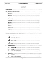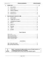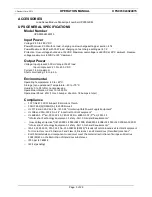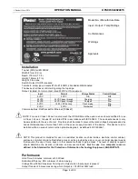
©
Panduit Corp. 201
4
OPERATION MANUAL
UPS003024024015
Page: 11 of 29
2.2.5. GROUND
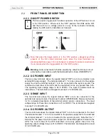
The terminal above the legend GND should be connected to the equipment ground.
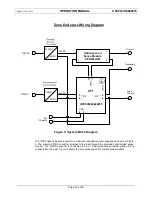
2.2.6. CON-Control Relay
The two terminals below the legend “CON” provide a normally open, single pole-
single throw (Form A) relay contact. The status of the relay follows the charge status
indicator as shown in table below.
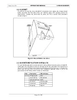
2.2.7. ETHERNET
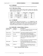
The Ethernet port marked below the legend <…> is a standard RJ-45 type
receptacle. This port should be connected to a router running a DHCP server. The
UPS will obtain an IP address from the DHCP server which will make it available to
provide status via a web browser on a PC running on the same network. This
connection is optional as the UPS can be operated without a connection to a PC.
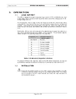
2.2.8. MOD LED
–
Module Status Indicator
Indicator State
Summary
Requirement
Steady Off
No Power
If no power is supplied to the device, the module
status indicator shall be steady off.
Steady Green
Device Operational
If the device is operating correctly, the module
status indicator shall by steady green.
Flashing Green
Standby
If the device has not been configured, the
module status indicator shall be flashing green.
Flashing Red
Minor Fault
If the device has detected a recoverable minor
fault, the module status indicator shall be
flashing red.
NOTE: An incorrect or Inconsistent configuration
would be considered a minor fault.
Steady Red
Major Fault
If the device has detected a non-recoverable
major fault, the module status indicator shall be
steady red.
Flashing
Green/Red
Self-Test
While the device is performing is power up
testing, the module status indicator shall be
flashing green/red.
Table 1: Module Status Indicator
Input
Output
Charge Status
Control Output
0 VDC
0 VDC
N/A
Off
24 VDC
24 VDC pass through
Charging
On
24 VDC
24 VDC pass through
Charged
On
0 VDC
18-22 VDC backup
Discharging
On
0 VDC
0 VDC
Discharged
Off


