©
Panduit Corp. 2013
OPERATION MANUAL
UPS LSM
Page: 6 of 6
Wiring Diagram
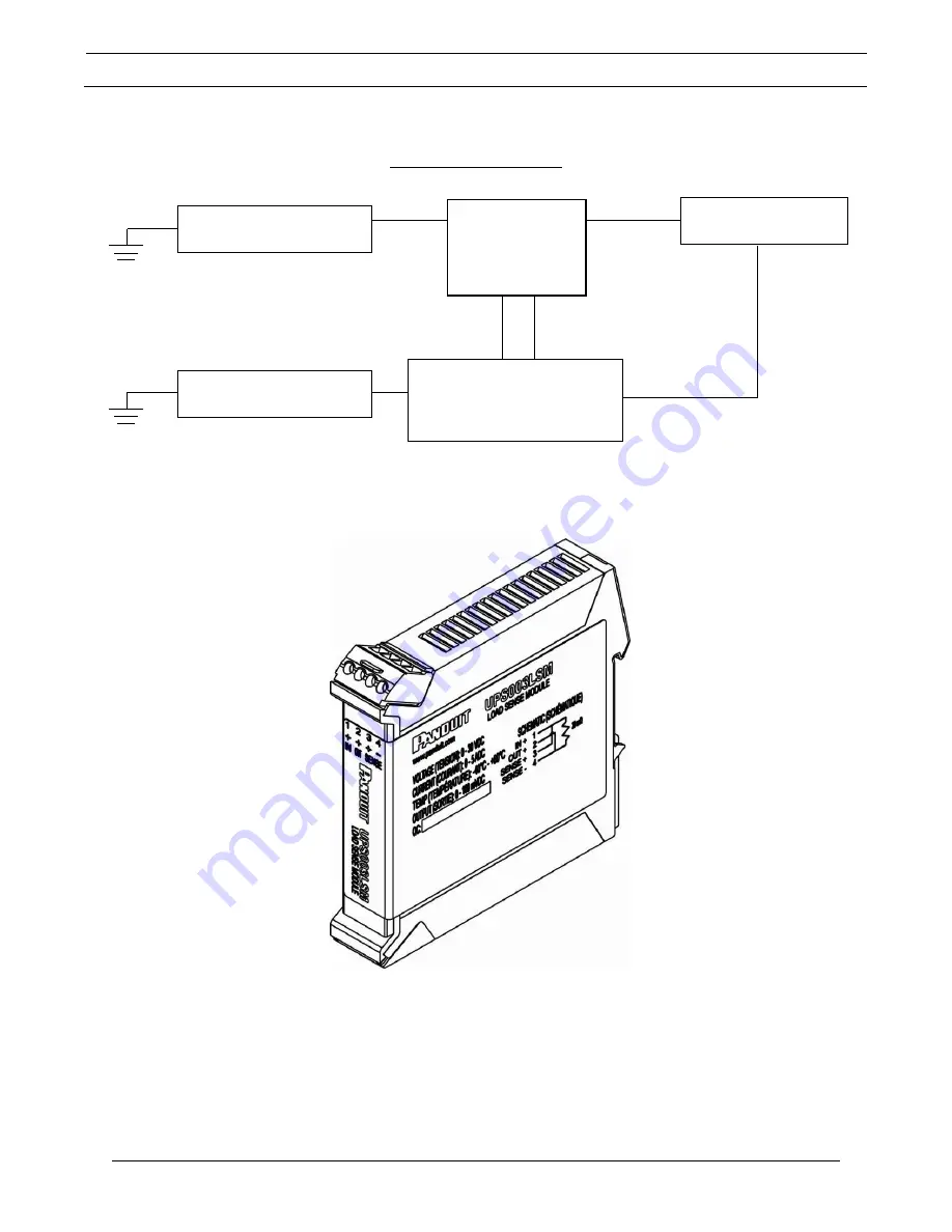
Figure 2: System Block Diagram
Figure 3: Load Sense Module
Pins 3 and 4 of the load sense module are connected to the sense input terminals of the UPS.
Note that pin 3 of the current sense resistor must be connected to the “+” sense terminal and
pin 4 of the current sense resistor must be connected to the “-“sense terminal. Note that these
connections may not be reversed. These connections allow the UPS to measure the current
flow to the load under normal operation so that it can predict the run time when backup power
is being provided by the UPS.
Primary Power Supply
24 VDC
Secondary Power Supply
24 VDC
UPS003LSM
20 m
Ω
Electrical Load
A
B
Uninterruptible Power Supply
(UPS)
1
2
3
4
Summary of Contents for UPS003LSM
Page 8: ......


