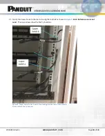
V00028CA Rev03
www.panduit.com
Page
12
of
18
25.
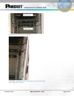
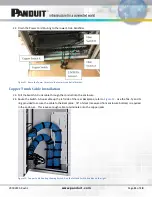
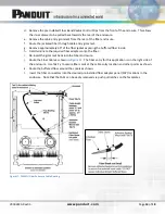
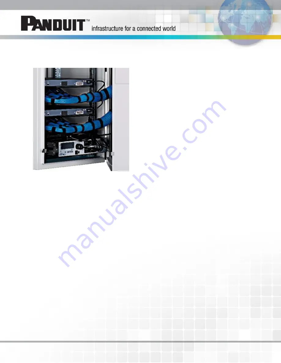
Attach the cables to the installed Strain Relief Bar using Tak-Ty in the miscellaneous carton. This is shown in
Figure 13: Switch-A (lower) and Switch-B (upper) copper cable bundles attached to strain relief bars.
26.
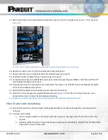
Bundle the cable in sets of (4) to be installed into the patch panel.
27.
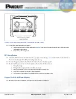
Remove the (12) snap-in faceplates from the installed lower patch panel.
28.
Feed the bundles of cables through the openings in the panel.
29.
Terminate the cables onto CJ688TGYL copper jacks (ordered separately) per PN403L,
TX6 PLUS and TX5e UTP
Jack Module Installation Instructions
.
30.
Snap the jacks into the removable snap-in faceplates from step 27 per PN207C,
Mini-Com Modular Faceplate
Patch Panel Installation Instructions
.
31.
Reinstall the faceplates onto the patch panel in the desired locations.
32.
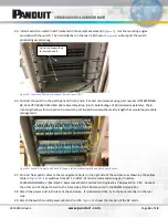
Optional: Print and apply the supplied labels and covers (
) to the front of the patch panel. Use a
Panduit LS9 printer to create TIA-606 compliant labeling.
33.
Repeat steps 23 through 32 for the Switch-B copper trunk cable and upper patch panel.
Fiber Trunk Cable Installation
34.
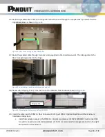
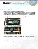
Pull the Fiber Switch-A and Fiber Switch-B (if applicable) fiber trunk cables through the conduit(s) into the
enclosure.
35.
If using armored cable:
a.
Cut the armored cable for 155 inches inside the enclosure. Leaving a stub of bare armor above the
conduit.
b.
Optional: Utilize Panduit’s Armored Cable Grounding Jumper Kit (ACG24K, ACG24K-500, ACG24KX-500)
to ground the armor of the cable.


