background image

 TRANSLATION OF THE ORIGINAL VERSION


HOKUBEMA Maschinenbau GmbH


Graf-Stauffenberg-Kaserne, Binger Str. 28 | Halle 120 

 DE 72488 Sigmaringen | Tel. +49 07571 755-0 

E-Mail: 

info@hokubema-panhans.de

 | Web: 

https://hokubema-panhans.de


Operating Manual   


Slot Drilling and Mortising Machine


PANHANS 116|10 


Machine Type: 

116|10 


Summary of Contents for 116 10

Page 1: ...inenbau GmbH Graf Stauffenberg Kaserne Binger Str 28 Halle 120 DE 72488 Sigmaringen Tel 49 07571 755 0 E Mail info hokubema panhans de Web https hokubema panhans de Operating Manual Slot Drilling and Mortising Machine PANHANS 116 10 Machine Type 116 10 ...

Page 2: ...onversions to the Machine 11 4 2 2 Residual Risks 12 4 2 3 Observe the Environmental Protection Regulations 13 4 2 4 Organisational Measures 13 4 2 5 Personnel Selection and Qualification Basic Duties 13 4 3 Safety Instructions for Specific Phases of Operation 14 4 3 1 Permitted Operations 14 4 3 2 Prohibited Operations 14 4 3 3 Before Working 14 4 3 4 Normal Operation 15 4 3 5 Special work within...

Page 3: ...ol Levers 28 10 5 Mounting the Eccentric Clamps 28 11 Commissioning 29 11 1 Clamping and Replacing the Drilling Tool 29 11 2 Switching ON an OFF 29 12 Operation 30 12 1 General Working Methods 30 12 1 1 Pre Settings 30 12 2 Mortising 30 12 3 Setting the Limit Stops 31 12 4 Adjusting the Drilling Depth Stop 31 12 5 Height Adjustment via Handwheel 31 12 6 Using the Dowel Drilling Unit 32 13 Optional...

Page 4: ... Maintenance and Inspection 38 15 1 Lubrication 38 15 2 Readjusting the Dovetail Guide 38 15 3 Readjusting the Cross Table Ball Guides 38 15 4 Readjust Motor Brake 39 15 4 1 Replacing the Motor Brake 40 15 5 Motor Brake with optional Variable Speed Control 40 16 Options and Accessories 41 17 Disassembly and Scrapping 42 EU Declaration of Conformity 43 ...

Page 5: ...e 31 Figure 22 Using the dowel drilling unit 32 Figure 23 Option Single lever operation 32 Figure 24 Option Variable double mitre fence 33 Figure 25 Option Pneumatic safety clamping cylinders 33 Figure 26 Option Dial gauge in the handwheel 33 Figure 27 Option Variable speed control 34 Figure 28 Option Safety protection cover 34 Figure 29 Option Collet chuck 34 Figure 30 Align the laser with the wo...

Page 6: ...et up troubleshooting in the work process removal of production waste and maintenance during maintenance servicing inspection repair and or during transport Apart from the operating manual and the legally binding accident prevention provisions applicable in the country and place of use the recognized technical regulations for safe and proper work must also be observed 1 1 Legal Notice All contents...

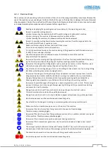
Page 7: ... to the obligation to wear protective goggles Non observance of these instructions may result in personal injury Reference to the obligation to wear a respiratory protection mask Non observance of these instructions may cause breathing difficulties and lung damage Reference to the obligation to wear safety shoes Non observance of these instructions may result in personal injury Possible dangerous ...

Page 8: ...ction lever to the right or left an infi nitely variable drilling speed via frequency converter is available as an option CE compliant and GS tested 3 2 Standard Equipment Smooth running cross support with adjustable ball guides for lateral and depth adjustment Two stop rods for infinitely variable adjustment of the mortise length in the X axis Dowel drilling device with pitches 16 22 25 and 32 mm...

Page 9: ...rsonnel of the machine The operating personnel is to be determined by the operator and must further meet the following requirements Basic technical knowledge e g apprenticeship as carpenter machine fitter etc and or practice in operat ing tilting spindle moulders resp woodworking machines Reading and understanding these operating and maintenance instructions In order to acquire the knowledge requi...

Page 10: ...ve modify or bypass any protective safety or monitoring equipment It is forbidden to modify or alter the machine without the written approval of the manufacturer supplier Faults or damage must be reported to the operator immediately eliminated without delay and repaired if necessary For repairs only original spare parts may be used All protective safety and monitoring devices must be regularly che...

Page 11: ... other materials requires prior consultation with and approval of the manufacturer Improper use can lead to danger to persons and to a defect or damage to the machine Only workpieces that can be safely placed and guided may be machined Metallic materials must not be machined The machine is not suitable for operation outdoors or in potentially explosive areas Permissible ambient temperature 5 40 C ...

Page 12: ...it Never reach into the running drilling bit Wear protective gloves when changing the tool Be aware of the danger of cutting through chips and splinters and never remove them from the danger area by hand and or while the machine is running Use suitable aids e g hand brushes Danger of being drawn in and increased risk of injury when wearing watches and jewellery Wearing watches and jewellery is pro...

Page 13: ...g manual Operators must not wear open long hair loose clothing or jewellery including rings There is a risk of in jury e g by getting caught or drawn in Observe the safety instructions and danger warnings on the machine and keep them complete and in legi ble condition In case of safety relevant changes to the machine or its operating behaviour shut down the entire system immediately and report the...

Page 14: ...ly use tools in perfect sharpened condition and with clean clamping surfaces Only clamp permitted approved tools in the drill chuck Before starting the drill spindle remove the drill chuck key Switch on and off only via the machine switch not with the connector Always check workpieces to be machined for foreign objects cracks and loose knots Only carry out adjustment work on the machine and the st...

Page 15: ...cylinder must be used for all drilling work The eccentric clamp or the optional pneumatic safety clamping cylinder must be clamped as close to the bore as possible Clamping round workpieces Attach a template with guide trough to the machine table clamp and ma chine the workpiece When using pneumatic safety clamping cylinders set the smallest possible stroke Clamping long workpieces For the safe su...

Page 16: ...the machine against unauthorised use and never leave it unattended in an unsecured condition Clean the machine with an industrial hoover avoid compressed air 4 3 7 Operator Training It is important that all users of table milling machines are adequately instructed in the use setting and operation This concerns in detail Possible hazards that may occur when working with the machine The basics of ma...

Page 17: ...er the drill chuck has an electrical interlocking device Art No 4611 4 3 11 3 Pneumatic Safety Clamping Cylinders 2 Pieces The workpieces are clamped safely and user friendly by a pneumatic safety cylinder The useful stroke of 100 mm allows a large adjustment range of different workpiece thicknesses without separate adjustment The cylinder is a sophisticated clamping system which generates a high ...

Page 18: ...ary Risk of crushing On all moving parts guides stops fences and clamping devices Danger of crushing between moving parts and in the clamping area of clamping devices Mild to severe inju ries contusions and or fractures of hands and fingers Keep hands out of the danger and clamping areas e g between workpiece and clamping element Risk of ejection On the tool chuck Increased danger if the spanner o...

Page 19: ... Motor brake mechanical electronic with option variable speed control Suction nozzle Ø 100 mm Space requirement approx 1600 x 1600 mm Weight approx 200 kg net seaworthy packed approx 320 kg Nameplate Figure 2 Name plate Manufacturer Expandability The machine is prepared for the later addition of special ac cessories see chapter 16 from the extensive manufac turer portfolio If you would like to ret...

Page 20: ...ugh there is a correlation between emission and immission levels it cannot be reliably deduced whether additional precautionary measures are necessary or not Factors that may affect the current immission level at the workstation include the duration of exposure the nature of the workspace other noise sources e g the number of machines and other adjacent operations The permissible workstation value...

Page 21: ...BA_PH_116 10_EN_12 22 docx 21 6 Dimensions Figure 4 Dimensions top view 1010 510 460 1280 ...

Page 22: ... Danger to life when using a forklift truck Keep a sufficient distance from the forklift truck and watch its speed Vehicles with combustion engines also produce toxic exhaust gases Wear a breathing mask if necessary 7 3 Installing the Machine Lift the machine slightly by the push bar at the front move it to the final place of use and park it The machine must be placed on a level solid and vibratio...

Page 23: ...sport vehicle must always be clean and dry The lashing straps used must be suitable for the total weight of the machine see section 5 1 Fastening on the loading area is done by lashing down This means that the transport pallet is secured by frictional locking The load is pressed so firmly onto the loading surface that it can no longer slip The clamp ing tool should have a high STF value at the fri...

Page 24: ...n system must start automatically When flexible suction hoses are used they must be flame retardant All parts of the extraction system including hoses must be included in the earthing measure 7 6 1 Air Speed The air speed must be set in such a way that with the extraction line connected and the tools stationary an average air speed of 20 m s 565 m h with dry chips and a negative pressure of 600 Pa...

Page 25: ...Observe the correct direction of rotation of the drill spindle If the direction of rotation is wrong two outer conductors must be interchanged 8 1 Back up Fuses on site Motor 1 3 1 7 kW The fault loop impedance and the suitability of the overcurrent protection device must be checked at the installation site of the machine 400 V 16 A slow Supply cable Cu 5 core The cross section must be determined ...

Page 26: ... lever for drilling depth 14 Hand wheel for height adjustment 15 Star grip for handwheel clamping 16 Height adjustment scale 17 Drill depth stop 18 Clamping for drill depth stop 19 Three jaw drill chuck 20 Clamping limit stops 21 Limit stops for mortise length 22 Dowel drilling unit 23 Star grip for drill depth clamping 24 Locking bolt for dowel drilling unit 25 Suction nozzle 26 Push handle 27 Mo...

Page 27: ...e place in case the machine needs to be transported at a later date 10 2 Mounting the Dowel Drilling Unit Figure 9 Mounting the dowel drilling unit The dowel drilling unit is supplied completely pre assem bled It only needs to be mounted on the drilling table with two screws Pull the locking bolt 24 and turn it by 90 Unscrew the two screws S mounted in the table Place the dowel drilling unit 22 on...

Page 28: ...and screw them tightly to the hinge bolts G In case of misalignment turn guide blocks F by 180 10 5 Mounting the Eccentric Clamps Figure 12 Mounting the eccentric clamps The two eccentric clamps included in the scope of delivery are mounted on the right and left of the table top Push the cross piece 9 onto the support bolt 8 and fix it with the corresponding clamping lever Fasten the eccentric cla...

Page 29: ...huck Before switching on the machine make sure that the tool is clamped securely and tightly After the drilling work has been completed the drilling bit must be removed as there is an increased risk of injury due to the protruding tool 11 2 Switching ON an OFF Clamp the drilling bit centrally before switching on and remove the drill chuck spanner Figure 14 Switching ON and OFF Switching ON Drillin...

Page 30: ...ers 12 or 13 to move the drill support in transverse or longitudinal direction 12 2 Mortising The drilling of a mortise is carried out according to the sequence shown in Figure 17 Figure 17 Mortising sequence Figure 18 Drilling out a mortise 1 After the pre settings 12 1 1 a hole is drilled as start and end point see distance D until the depth stop is reached Note The start and end point for the m...

Page 31: ...the case of deep mortises always gradually increase the drilling depth to connect the inter mediate holes together according to Figure 17 Drilling too deep in one step can destroy the tool and or overload the motor 12 5 Height Adjustment via Handwheel The height of the drill support is adjusted using the handwheel on the operating side The setting 0 on the scale means that the tip of the drill is ...

Page 32: ...r the following options can be found in chapter 16 Options and Accessories 13 1 Option Single Lever Operation Figure 23 Option Single lever operation With the optional single lever operation the longitudinal and transverse movement of the drilling unit is carried out centrally via just one lever In addition the locking bolt of the dowel drilling unit can be lifted off the raster rod and re engaged...

Page 33: ...ed air network Operating pressure max 6 bar Figure 25 Option Pneumatic safety clamping cylinders Operation The pneumatic clamping cylinder has a generous stroke of max 100 mm Adjust the height of the clamping cylinder to the work piece so that the stroke is sufficient for clamping Use the full stroke for different workpiece thicknesses Clamp workpiece Push the hand slide valve V forwards towards t...

Page 34: ...r work on the frequency inverter may only be carried out by an au thorised electrician Danger from electric shock at the frequency inverter After switching off the main switch wait at least 15 minutes before working on the frequency inverter 13 6 Option Safety Protection Cover Figure 28 Option Safety protection cover This safety guard prevents the drilling spindle from starting unintentionally The...

Page 35: ...ctory and must not be adjusted under any circumstances The installed laser must not be replaced by a laser of a different type No additional optical devices or attachments may be used Laser repairs may only be carried out by the laser manufacturer or by authorised persons Note that the laser beam may be reflected by reflective surfaces e g the table top or other bare machine parts and or accessori...

Page 36: ...ntional type AA batteries or expose them to temperatures above 85 C Please dispose of the used batteries in a professional and environmentally friendly manner 13 8 5 Realignment of the Laser If the laser is misaligned or the centre of the drilled hole is no longer in exact alignment with the laser beam the laser must be realigned The lateral adjustment is made via the oblong hole on the mounting b...

Page 37: ...arts Workpiece incorrectly clamped Defective drill Drill speed too high Clamp workpiece correctly Use new drill Reduce speed Handwheel for height adjustment is stiff Handwheel clamp tightened Dovetail guides of the drill are support heavily soiled Loosen clamping Clean guides Support for the height adjustment has too much play Dovetail guide must be readjusted Adjust the guide evenly see 15 2 The ...

Page 38: ...Due to the different operating conditions it is not possible to determine in advance how often a wear check inspection or maintenance is required Inspection intervals are to be determined appropriately according to the respective operating conditions 15 1 Lubrication Every 3 months the dovetail guides of the drilling support and the ball guides of the cross table must be lubricated with a thin bod...

Page 39: ...und the fan cover and remove the fan cover Figure 38 Loosen the securing screw 4 Now loosen the locking screw on the front side with a flat blade screwdriver by approx 1 turn Figure 39 Adjusting nut for brake lining 5 With an SW27 open end spanner the brake can now be adjusted outwards or inwards via the centred adjusting nut Figure 40 Gap to be adjusted 6 The gap dimension S between the inside I ...

Page 40: ...our motor Then contact our customer service phone 0049 7571 755 0 to order a suitable new brake 15 5 Motor Brake with optional Variable Speed Control On machines with the option Variable Speed Control the motor brake cannot be readjusted because there is no longer a mechanical brake The braking process is completely controlled by the frequency inverter If you still have problems braking the machin...

Page 41: ... quired from the customer 4612 SINGLE LEVER OPERATION With remote locking for the longitudinal and transverse movement of the drill motor including release and locking of the locking bolt on the dowel drilling unit instead of the 2 lever operation narrow workpieces can thus also be ma chined from the table side 4058 DIAL GAUGE IN HANDWHEEL With 0 1 mm display of height adjustment instead of scale ...

Page 42: ...n laws in force at the place of use regarding the disposal of industrial solid waste toxic and hazardous waste Hoses and plastic parts as well as other components that are not made of metal must be dismantled and recycled or disposed of separately Electrical components such as cables switches connectors transformers etc must be re moved and if possible recycled or otherwise disposed of in a qualif...

Page 43: ...hnical specifications in particular VBG 7j Machines and plants for working and processing wood and similar materials Accident prevention regulations of the German Timber Employers Liability Insurance Association DIN 45 635 Noise measurement test TRGS 553 Dust emission test BGI739 Wood dust occupational safety and health protection during collection extraction and storage The notified body 0392 Fac...

Reviews: