background image

TRANSLATION OF THE ORIGINAL VERSION


HOKUBEMA Maschinenbau GmbH


Graf-Stauffenberg-Kaserne, Binger Str. 28 | Halle 120 

 DE 72488 Sigmaringen | Tel. +49 07571 755-0 

E-Mail: 

info@hokubema-panhans.de

 | Web: 

https://hokubema-panhans.de


Operating Manual   


Tilting Spindle Moulders / Table Milling Machines 


PANHANS 245|100, 245|200 and 245|300 


Machine-Types: 

245|100, 245|200 and 245|300 


Summary of Contents for Ultimo-Touch 245/100

Page 1: ...g Kaserne Binger Str 28 Halle 120 DE 72488 Sigmaringen Tel 49 07571 755 0 E Mail info hokubema panhans de Web https hokubema panhans de Operating Manual Tilting Spindle Moulders Table Milling Machines...

Page 2: ...sidual Risks 14 4 2 4 Observe the Environmental Protection Regulations 15 4 2 5 Organisational Measures 15 4 2 6 Personnel Selection and Qualification Basic Duties 16 4 3 Safety Instructions for Speci...

Page 3: ...7 6 2 Existing negative pressure at 20 m s 28 8 Electrical Connection 29 8 1 Back up Fuses on site 29 8 2 Machine Socket 29 9 Components and Control Elements 30 10 Commissioning 31 10 1 Switching ON...

Page 4: ...ystem 51 16 8 Calibration Unit Zeromaster 51 16 9 Tenoning and Slotting Device Type 1376 52 16 9 1 Operation 52 16 9 2 Table for Angular Cuts 52 16 9 3 Adaptation to the Machine Table only required fo...

Page 5: ...ontrol Elements 30 Figure 12 Warning climb milling mode 31 Figure 13 Emergency Stop Push Buttons 32 Figure 14 Milling arbor with quick clamping device 32 Figure 15 Marking for upper spacer ring 32 Fig...

Page 6: ...e support 51 Figure 51 TM 300 Machine Access Control System 51 Figure 52 Calibration unit Zeromaster 51 Figure 53 Tenoning guard 1376 52 Figure 54 Angle ranges position of the screws 52 Figure 55 Adap...

Page 7: ...ork process removal of pro duction waste and maintenance during maintenance servicing inspection repair and or during transport Apart from the operating manual and the legally binding accident prevent...

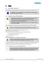
Page 8: ...ce to the obligation to wear protective goggles Non observance of these instructions may result in personal injury Reference to the obligation to wear a respiratory protection mask Non observance of t...

Page 9: ...r with the CNC compatible automatic tool change system HSK63 F The height and tilt adjustment is carried out automatically via the UT 300 position control unit The finely planed cast iron machine tabl...

Page 10: ...cal knowledge e g apprenticeship as carpenter machine fitter etc and or practice in operat ing tilting spindle moulders resp woodworking machines Reading and understanding these operating and maintena...

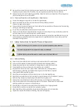
Page 11: ...y or bypass any protective safety or monitoring equipment It is forbidden to modify or alter the machine without the written approval of the manufacturer supplier Faults or damage must be reported to...

Page 12: ...mm 50 mm 1 not retrofittable Machine access control via RFID key system with personalised keys Milling fence types 302 311 and 320 for models 245 100 and 200 Single and double sided table top extensio...

Page 13: ...ger to persons and to a defect or damage to the machine Only workpieces that can be safely placed and guided may be machined Metallic materials must not be machined The machine is not suitable for ope...

Page 14: ...persons are not allowed to enter the installation area of the machine responsibility of the operator Be aware of possible tripping and slipping hazards on the floor Prevent possible hazards by keep in...

Page 15: ...Avoid leakage of hazardous substances by using suitable collection contain ers Ensure that the above mentioned substances are disposed of by a qualified dis posal company 4 2 5 Organisational Measure...

Page 16: ...ine are to be reported immediately after detection Any mode of operation that compromises safety is prohibited Sufficient lighting around the machine must be ensured at least 500 Lux 4 3 1 Before Work...

Page 17: ...at an angle of approx 5 to the feed direction and keep the opening to the fence as small as possible Manual feeding When feeding the workpiece manually place the hands flat on the workpiece with clos...

Page 18: ...m Secure the machine against unauthorised use and never leave it unattended in an unsecured condition Clean the machine with an industrial hoover avoid compressed air 4 4 Safe Working Practices Depend...

Page 19: ...ation Climb milling with manual feed involves considerable dangers This operation is only permitted with ap propriate devices and suitable tools If the machine is switched to climb milling this operat...

Page 20: ...ecurely fastened front cross fence as well as a kickback guard e g type 1648 see section 16 10 must also be used For very long workpieces use an auxiliary fence if necessary Quick clamps acting either...

Page 21: ...tive cover to protect the tool from the top With the insert rings included as standard the table opening can be adapted to the tool diameter to keep it as small as possible The service door at the fro...

Page 22: ...he event of tool breakage Increased risk of in juries or even death due to entrapment of hands fingers clothing jewellery and long hair Use all available tool covers and fence bridges Do not push work...

Page 23: ...0 Programs each 4 5 20 Programs each 4 500 100 Programs each Suction Nozzles mm 2 pieces 120 2 pieces 120 2 pieces 120 Net Weight kg approx 800 approx 880 approx 1050 Nameplate Figure 2 Nameplate Manu...

Page 24: ...machines and other adjacent operations The permissible workstation values can also vary from country to country However this information should enable the user to make a better assessment of hazard a...

Page 25: ...ns without Table Extensions 6 2 With Table Extensions Option Figure 5 Dimensions with Table Extensions 1100 1340 760 800 Standard table larger table option 1324 1380 1480 89 120 Table extension 350 11...

Page 26: ...g hazards when placing the machine from the pallet to the floor by means of a forklift truck or similar Pay particular attention to your hands and feet and wear safety shoes and protective gloves as a...

Page 27: ...oint Z All 4 lashing straps must be individually tensioned on the loading area The machine may only be lashed at the four lashing points Z provided Please note the following when lashing in the transp...

Page 28: ...of the extraction system Version Connection terminals Version Connection terminals 245 100 13 14 of contactor Q4 245 200 and 245 300 13 14 of contactor 1QA1 Installation only by a qualified electricia...

Page 29: ...rs must be interchanged 8 1 Back up Fuses on site Motor 5 5 kW 7 5 kW The fault loop impedance and the suitability of the overcurrent protection device must be checked at the installation site of the...

Page 30: ...splinter tabs 2 x 17 Swivel arm for control panel 7 Milling fence protective bonnet 18 Position of terminal box and machine socket 8 Adjusting screw partial fence 19 Control cabinet position 9 Vernier...

Page 31: ...ticlockwise Switchover only possible at standstill Figure 12 Warning climb milling mode Climb Milling Cutter turns clockwise Switchover only possible at standstill Avoid climb milling as this consider...

Page 32: ...dle by hand so that the clamping screw S is accessible Press one of the two emergency stop buttons 4 and leave it locked Figure 14 Milling arbor with quick clamping device 1 Loosen the clamping screw...

Page 33: ...then turn the spindle manually until it engages Figure 16 Remove dust protection cap Figure 17 Loosen remove the milling arbor with spanner 4 There is a magnet in the handle of the clamping key This c...

Page 34: ...ol chang ers are used to change and clamp the complete milling arbor without the need for tools The loosening as well as the clamping of the milling arbor is completely elec tromechanical which allows...

Page 35: ...12 Positioning the Tool Height and Tool Angle The positioning of the tool height and the tool angle is done via the position controller see section Height and Angle Positioning in the separately enclo...

Page 36: ...245 300 These models have a frequency inverter that allows infinitely variable speed regulation from 1 500 to 10 000 rpm The speed is adjusted via the touchscreen control See chapter Speed Settings in...

Page 37: ...4 Figure 25 Move centrally over milling spindle Remove dirt and chips from the machine table and the underside of the fence Move the fence over the machine table with the help of a second person with...

Page 38: ...from the table top before adjusting the milling fence For maintenance of your fence please refer to section 18 1 14 2 1 Fence Type 301 Figure 28 Operating elements Fence Type 301 With type 301 the tot...

Page 39: ...ting off and removing the fence Remove clamping levers 3 and 6 by unscrewing them lift off the fence and remove it Due to the heavy weight of the fence this operation should be carried out by 2 person...

Page 40: ...hood unlocking rear left Fence plate adjustment Loosen the star grip 8 and push the fence plate 1 to the desired position Then retighten the star grip 8 Al ways adjust the plates so that they cover as...

Page 41: ...en the fence can be lifted off and removed Due to the heavy weight of the fence this operation should be carried out by 2 persons or with a suitable hoist Lifting off with Swivel away Device Option Fi...

Page 42: ...ample A target position of 15 0 mm is to be approached For example we start at approx 40 mm Slowly turn back the handwheel The right half of the display shows the direction of rotation as symbol Conti...

Page 43: ...posal of the old battery Fire explosion and burn hazard Never recharge the batteries used in the AP 10 or expose them to temperatures above 85 C Used batteries must not get into fire water or groundwa...

Page 44: ...the total fence The detailed procedure is described in the separately enclosed operating manual of the control unit BA_PH_UT300_EN refer to chapter Fence positioning section Fence Type 311 Folding up...

Page 45: ...pter Fence Positioning section Swivel away Devices 14 2 5 Fence Type 320 Figure 37 Operating elements Fence Type 320 With the type 320 the total and par tial fence are adjusted completely automaticall...

Page 46: ...o people or with a suitable hoist e g an indoor crane Danger of crushing hands and fingers between fence and machine table Wear protective gloves when lifting or placing the fence Acute risk of injury...

Page 47: ...d justed using the two clamping levers 9 at the rear of the fence parallel to the table top It can be mounted either above or be low the tool The height of the workpiece hold down and the contact guar...

Page 48: ...engages again 15 2 TYPE 1624 CENTREX Option The protection and pressure device type 1624 CENTREX is used for the safe fixing of workpieces during manual milling operations It fits all the milling fenc...

Page 49: ...ion 1 Height adjustment 2 Fold out guide fingers 3 Move fence plates 16 2 Table Slide Plate Figure 46 Optional Table Slide The patented table slide plate T has coated surfaces and ensures a safe and q...

Page 50: ...completely unscrewed fence type 320 The lift off command is given via button on the touchscreen control unit The detailed procedure for operating the device is described in the separately enclosed ope...

Page 51: ...ith the user data bank only au thorised personnel can start the machine by using a personalised RFID key Included is the TM 300 system with 5 person alised user keys and 1 full access key for au thori...

Page 52: ...falls down Wear safety shoes with steel toecaps Note for possible retrofitting If the device is retrofitted later it must be mechanically adapted to the machine table on site For this purpose the tabl...

Page 53: ...his purpose two M12 threads must be fitted bore diameter 10 2 mm Fasten the tenoning device with M12 x 30 hexagon screws and washers 16 9 4 Supplementary Protective Cover 1641 Option The protective co...

Page 54: ...ith a useful length of 1750 to 2750 mm Article number see section 20 5 16 12 Roller Table Figure 58 Roller table The optional roller table has a stop fixture an eccentric clamp as well as a clamping t...

Page 55: ...ely variable feed speed from 2 18 m min as well as clockwise anti clockwise rotation Rotate to insert horizontal vertical Max outreach of 1 050 mm Easy swivelling away and positioning with memory lock...

Page 56: ...Machine does not start No voltage Check power supply Control fuse defective Replace fuse wiring diagram Main switch defective Replace main switch Drive motor defective Replace motor V belt defective...

Page 57: ...al commissioning and after signifi cant modification If the motor no longer brakes within 10 seconds when switching off it is essential to contact the customer service Do not use the machine until the...

Page 58: ...is dragging which means that it has been adjusted too excessively If the brake is dragging the readjustment made must be minimally reversed again Now turn the brake release switch back to Normal Oper...

Page 59: ...cate with a thin bodied oil if necessary X Apply a few drops of oil to the threads of the clamping adjustment levers X Clean swivel segments from resin and wood residues and lubricate with a thin bodi...

Page 60: ...et using the adjusting screw S To do this approach it step by step by first tightening the adjusting screw S only slightly in clockwise direction swinging the lever E back again and then checking the...

Page 61: ...from above with a strong thumb pres sure approx 2 kg 10 With correct pretension the belt must only be able to be pushed downwards X by max 5 mm 11 If a new belt is installed it must only be possible...

Page 62: ...r and secure against unintentional restarting Lock the main switch with a padlock Figure 67 Change lubricator Figure 68 Activation with activation screw Open the front service door and unscrew the use...

Page 63: ...Access from above before remove insert rings table slider weekly lubricate with fine oil 6 Optional HKS 63 quick tool change system Under the lower milling spindle bearing open front service door mon...

Page 64: ...R TABLE TOP 1100 X 760 MM With coated surfaces For fast comfortable and tool free adjustment to different tool diameters up to max 240 mm incl front table insert with quick lock up to tool diameter 15...

Page 65: ...ing levers Die cast aluminium milling fence with 2 flat milled cast iron fence plates 500 mm long with aluminium splinter tongues tool diameter max 250 mm 4625 MILLING FENCE 302 Manual total and parti...

Page 66: ...eces during manual milling work the spe cial shape of the pressure shoes ensures precise workpiece guidance during all milling work attached to the milling fence can be folded upwards Usable instead o...

Page 67: ...clamping length 180 mm 4634 ARBOR HSK 63 F 50 MM See Art No 4650 but clamping length 160 mm 4652 ARBOR HSK 63 F 1 See Art No 4650 but clamping length 140 mm 4636 COLLET CHUCK HSK 63 F A dimension tota...

Page 68: ...e length 1750 to 2750 mm 4418 TENONING AND SLOTTING DEVICE 1376 Mounted on the machine table for light tenoning and slotting work with eccentric clamp and adjustable mitre fence Sliding length 710 mm...

Page 69: ...e for user database TM 300 content 10 pieces 4670 MASTER KEY Red for user database TM 300 content 1 piece 4671 TOOL DATABASE20 FOR 10 TOOLS With 20 programs per tool 4614 TOOL DATABASE20 FOR 20 TOOLS...

Page 70: ...ion laws in force at the place of use regarding the disposal of industrial solid waste toxic and hazardous waste Hoses and plastic parts as well as other components that are not made of metal must be...

Page 71: ...version provided complies with the following directives Machinery Directive 2006 42 EG EMC Directive 2004 108 EG Applied guidelines in particular DIN EN 848 1 The notified body 0392 Fachausschuss HOL...

Reviews: