BA_PH_245-100-300_EN_06-22.docx
28
7.6
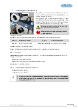
Connecting the Extraction Unit
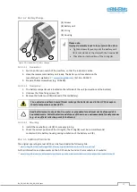
Figure 8: Suction nozzles
The machine must be connected to an effective extraction sys-
tem on-site. The two extraction nozzles (
1
) and (
2
) each have
an outer diameter of 120 mm.
For transport reasons, the lower extraction socket in the stand
is mounted with the connection facing inwards (
1a
). Before
connecting the extraction unit, it must first be unscrewed,
turned to the outside and then mounted again (
1b
).
When the machine is switched on, the extraction
system must start automatically.
When flexible suction hoses are used, they must
be flame-retardant.
Two signal generator lines must be connected for automatic switching of the extraction system:
Version
Connection terminals
Version
Connection terminals
245|100
13
+
14
of contactor
-Q4
245|200
and
245|300
13
+
14
of contactor
-1QA1
Installation only by a qualified electrician!
All parts of the extraction system, including hoses, must be included in the earthing measure.
7.6.1
Air Speed
The air speed must be set in such a way that, with the extraction line connected and the tools stationary, an
average air speed of
-
20 m/s (1450 m³/h) with dry chips,
-
28 m/s (2050 m³/h) with moist chips (moisture 18 % or more)
is achieved at the extraction nozzles.
7.6.2
Existing negative pressure at 20 m/s
-
on the milling fence: 640 Pa
-
under the table top: 300 Pa
•
The air velocity must be checked before initial commissioning and after significant changes.
•
The extraction system must be checked daily for obvious defects after initial commissioning
and monthly for effectiveness.
2
1b
1a


