Installation Instructions
L[X]A[X]M4[X]-7-42
SW3-1078 - v1
1. Introduction
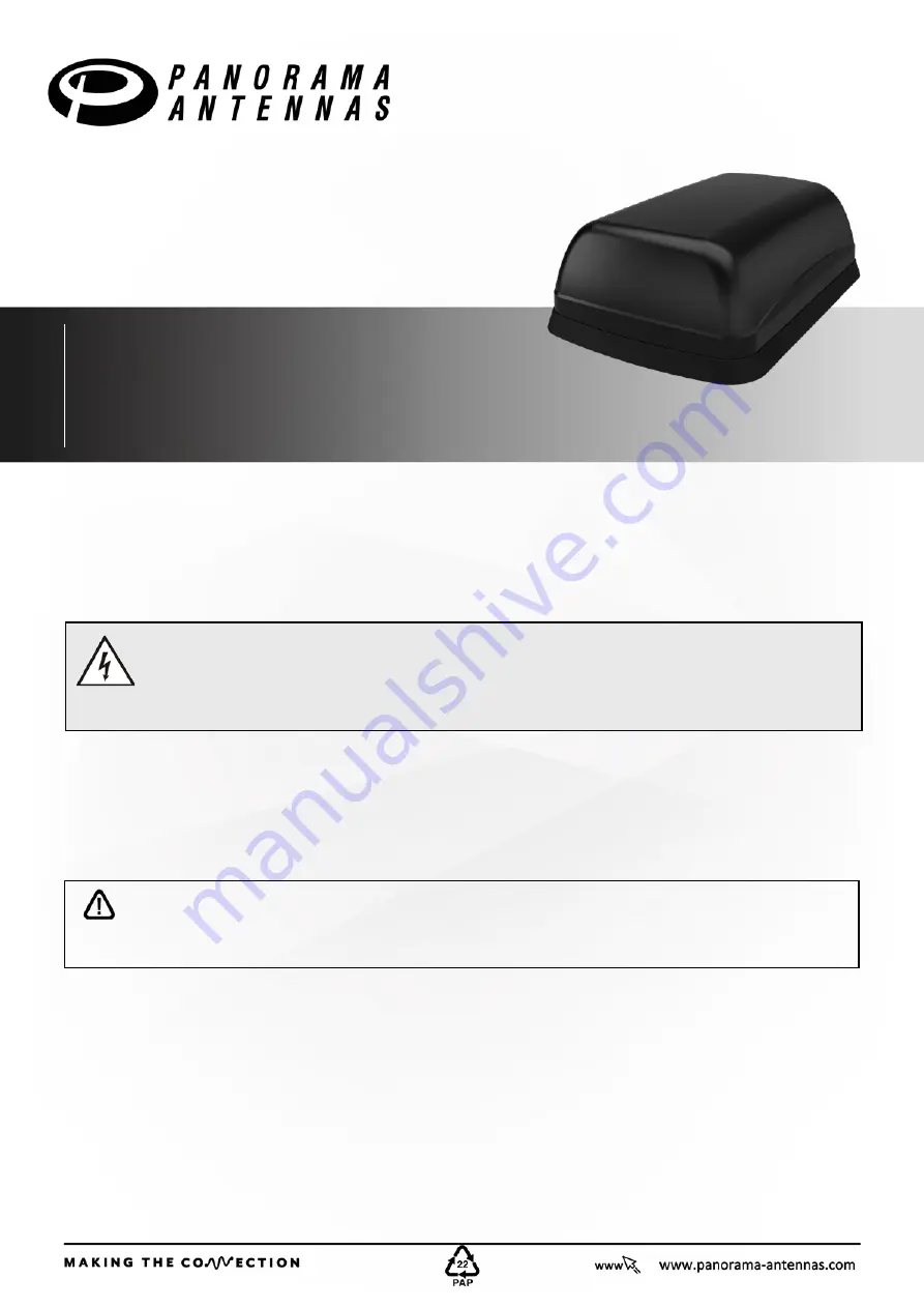
The L[X]A[X]M4[X]-7-42[-X] MiMo antenna is designed to be a one size fits all solution for IOT applications. The robust low profile housing contains 4x 4G
LTE / 5G NR elements covering 698-960/1427-4200MHz. Versions of the product are available with up to 4x WiFi elements supporting WiFi 6e
2.4/5.150-7.125GHz and optional L1 only or L1/L5 GPS/GNSS. The antenna is suitable for fitment to panels up to 4mm (0.15”) thick. A bracket for wall or
mast mounting is available as an optional accessory..
2. Mounting requirements and selecting location
The L[X]A[X]M4[X] -7-42 range can be mounted on a conductive or non-conductive panel. Select a mounting location, checking for panel
curvature to ensure that the antenna base will have a flat mounting surface if possible.
Ensure that there is adequate under panel clearance and that there are no obstructions under the panel. Measure to check for central position if
applicable. For optimal performance the antenna should, if possible, be mounted at least 300mm (1ft) away from other conductive objects on the mounting
panel.
3. Prepare and drill hole
Electrical Safety Note
LGA[X]M4[X]-7-42 contains an active L1 Band GPS/GNSS antenna. Rated voltage: 3-5VDC Rated current: 17mA maximum.
LG5A[X]M4[X]-7-42 contains an active L1/L5 Band GPS/GNSS antenna. Rated voltage: 3-5VDC Rated current: 37mA maximum.
The supply to these devices must be provided with over current protection of 1A maximum.
Important Note Regarding Sealing
It is important that the periphery of the antenna is sealed and that no moisture is allowed to penetrate under the antenna boot.
To ensure that the antenna base is effectively sealed against the mounting surface, care must be taken regarding curvature of the mounting panel.
It is highly recommended that the antenna is installed on a clean, flat and level surface. After installation, the compression of the rubber boot
against the mounting panel should be checked - If necessary, a small bead of neutral cure silicone sealant can be applied around the edge of the
mounting boot.
Mask panel area around hole position to protect fi nish. Drill a pilot hole, and then increase to 19mm (3/4”), ensuring that drill/ cutter bit does not
contact any parts under the panel. Clean area around the hole, carefully removing an burrs and all swarf.
4. Fitting the antenna
Note:It is recommended that the installation is carried out when the temperature is greater than 50°F (10°C) as the ideal temperature for the pad bonding
is 70°F (21°C) to 100°F (37°C).
Remove protective backing from underside of antenna, feed coaxial cables through panel. Position the antenna over the hole ensuring correct orientation
and stick to panel by applying firm, even, downward pressure. When fitting the nut, it is important to ensure that the cables are held centrally whilst the nut
is correctly started on the threads. The nut should fit freely by hand and only requires a final tighten by spanner to a recommended torque of 5Nm.
IMPORTANT: Do not exceed a torque of 5Nm (3.6ft/lbs) when tightening the securing nut.
EN

![Preview for 1 page of Panorama Antennas L[X]A[X]M4[X]-7-42 Installation Instructions Manual](http://thumbs1.mh-extra.com/thumbs/panorama-antennas/l-x-a-x-m4-x-7-42/l-x-a-x-m4-x-7-42_installation-instructions-manual_4925602-01.webp)
![Preview for 2 page of Panorama Antennas L[X]A[X]M4[X]-7-42 Installation Instructions Manual](http://thumbs1.mh-extra.com/thumbs/panorama-antennas/l-x-a-x-m4-x-7-42/l-x-a-x-m4-x-7-42_installation-instructions-manual_4925602-02.webp)
![Preview for 3 page of Panorama Antennas L[X]A[X]M4[X]-7-42 Installation Instructions Manual](http://thumbs1.mh-extra.com/thumbs/panorama-antennas/l-x-a-x-m4-x-7-42/l-x-a-x-m4-x-7-42_installation-instructions-manual_4925602-03.webp)
![Preview for 4 page of Panorama Antennas L[X]A[X]M4[X]-7-42 Installation Instructions Manual](http://thumbs1.mh-extra.com/thumbs/panorama-antennas/l-x-a-x-m4-x-7-42/l-x-a-x-m4-x-7-42_installation-instructions-manual_4925602-04.webp)
![Preview for 5 page of Panorama Antennas L[X]A[X]M4[X]-7-42 Installation Instructions Manual](http://thumbs1.mh-extra.com/thumbs/panorama-antennas/l-x-a-x-m4-x-7-42/l-x-a-x-m4-x-7-42_installation-instructions-manual_4925602-05.webp)
![Preview for 6 page of Panorama Antennas L[X]A[X]M4[X]-7-42 Installation Instructions Manual](http://thumbs1.mh-extra.com/thumbs/panorama-antennas/l-x-a-x-m4-x-7-42/l-x-a-x-m4-x-7-42_installation-instructions-manual_4925602-06.webp)
![Preview for 7 page of Panorama Antennas L[X]A[X]M4[X]-7-42 Installation Instructions Manual](http://thumbs1.mh-extra.com/thumbs/panorama-antennas/l-x-a-x-m4-x-7-42/l-x-a-x-m4-x-7-42_installation-instructions-manual_4925602-07.webp)
![Preview for 8 page of Panorama Antennas L[X]A[X]M4[X]-7-42 Installation Instructions Manual](http://thumbs1.mh-extra.com/thumbs/panorama-antennas/l-x-a-x-m4-x-7-42/l-x-a-x-m4-x-7-42_installation-instructions-manual_4925602-08.webp)
![Preview for 9 page of Panorama Antennas L[X]A[X]M4[X]-7-42 Installation Instructions Manual](http://thumbs1.mh-extra.com/thumbs/panorama-antennas/l-x-a-x-m4-x-7-42/l-x-a-x-m4-x-7-42_installation-instructions-manual_4925602-09.webp)
![Preview for 10 page of Panorama Antennas L[X]A[X]M4[X]-7-42 Installation Instructions Manual](http://thumbs1.mh-extra.com/thumbs/panorama-antennas/l-x-a-x-m4-x-7-42/l-x-a-x-m4-x-7-42_installation-instructions-manual_4925602-10.webp)


