background image

© 2001   PANORAMAdtv  ALL rights reserved

14

MON3-2A User Manual  P/N 821521 Rev-B.5

(Continued)

H

CVBS Out - BNC Connector (MSDI-1 SDI Option)

This connector supplies an analog CVBS encoded signal derived from the SDI input.  Automatic standards
sensing is accomplished by detecting 525 or 625 line signals.  525 line SDI input signals are encoded as an
NTSC output.  625 line SDI input signals are encoded as a PAL output. (MSDI-1 SDI option is required.)

I     CBAR On - Toggle Switch (MSDI-1 SDI Option)

This switch controls a color bar generator associated with each monitor. To view the input signal, place
this switch in the DOWN position. To activate the color bar generator, place this switch to the CBAR ON
(UP) position. (MSDI-1 SDI option is required.)

Note:

An active SDI input must be present for the color bars to function.

J

Tally Control - DB-25 Connector

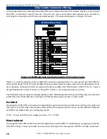
This 25 pin sub-miniature female “D” connector allows you to tally individual monitor front panel Tally
indicators. Full connection instructions are described on page 18.

Rear Panel Features

Section 2: Operation

Summary of Contents for MON3-2A

Page 1: ...t Panel Features Rear Panel Features Section 3 Technical Information Tally Control Connector Wiring MSDI 1 SDI Option Field Upgrade MON3 2A 2U Triple LCD Video Monitor With Analog Inputs and Loop thro...

Page 2: ...ing walked on or pinched particularly at plugs convenience receptacles and the point where they exit from the apparatus 11 Only use attachments accessories specified by the manufacturer 12 Use only wi...

Page 3: ...NORAMAdtv ALL rights reserved 3 MON3 2A User Manual P N 821521 Rev B 5 Sect 1 General Features and Specifications General Features and Specifications Description Features Applications Specifications S...

Page 4: ...The LCD module circuitry automatically detects and indicates the presence of NTSC or PAL signals with front panel LED indicators Each LCD display has its own front panel trim pot controls for color t...

Page 5: ...ures and specifications subject to improvement without notice General Specifications Section 1 General Features and Specifications Operating Tempurature Indicators Connectors Standard Unit Dimensions...

Page 6: ...2001 PANORAMAdtv ALL rights reserved 6 MON3 2A User Manual P N 821521 Rev B 5...

Page 7: ...2001 PANORAMAdtv ALL rights reserved 7 MON3 2A User Manual P N 821521 Rev B 5 Operation Installation Front Panel Features Rear Panel Features Section 2...

Page 8: ...2001 PANORAMAdtv ALL rights reserved 8 MON3 2A User Manual P N 821521 Rev B 5 Section 2 Operation Installation Figure 2a MON3 2A Chassis Dimensions...

Page 9: ...l support rails Rear support is not required LCD Monitor Viewing Position To obtain the best operator s viewing angle mount the MON3 2A as nearly straight on to the operator s position as possible 0 d...

Page 10: ...ontrols TINT Tint adjust for desired image color hue NTSC only CHROMA Color Saturation adjust for desired amount of image color saturation BRIGHT Brightness adjust for desired screen brightness CONT C...

Page 11: ...2001 PANORAMAdtv ALL rights reserved 11 MON3 2A User Manual P N 821521 Rev B 5 Figure 2b MON3 2A Front Panel Features Section 2 Operation...

Page 12: ...ections to down stream equipment are supplied here If you supply down stream equipment from this connector ensure you set the TERM LIFT toggle switch Item D to the LIFT DOWN position If no other equip...

Page 13: ...APPROVED IS UL SEE SIDE FOR ADDI POWER SUPPLY 650 589 5676 FAX 650 589 1355 South San Francisco CA 94080 711 Grandview Drive PANORAMAdtv TERM LIFT 3A 2A IN CVBS 1A LOOP IN CVBS CVBS TERM LIFT LOOP CVB...

Page 14: ...option is required I CBAR On Toggle Switch MSDI 1 SDI Option This switch controls a color bar generator associated with each monitor To view the input signal place this switch in the DOWN position To...

Page 15: ...APPROVED IS UL SEE SIDE FOR ADDI POWER SUPPLY 650 589 5676 FAX 650 589 1355 South San Francisco CA 94080 711 Grandview Drive PANORAMAdtv TERM LIFT 3A 2A IN CVBS 1A LOOP IN CVBS CVBS TERM LIFT LOOP CVB...

Page 16: ...2001 PANORAMAdtv ALL rights reserved 16 MON3 2A User Manual P N 821521 Rev B 5 Section 2 Operation...

Page 17: ...2001 PANORAMAdtv ALL rights reserved 17 MON3 2A User Manual P N 821521 Rev B 5 Technical Information Section 3 Tally Control Connector Wiring MSDI 1 SDI Option Field Upgrade Instructions...

Page 18: ...the LEDs interface with TTL levels You can design illumination circuits as shown by using TTL buffers or by using transistors as switches TheTallyindicatorsarecapableofdisplayingthreecolors Illuminati...

Page 19: ...1 PANORAMAdtv ALL rights reserved 19 MON3 2A User Manual P N 821521 Rev B 5 Tally Control Connector Wiring Section 3 Technical Information Figure 3b MON3 2A Sample Tally Connections MON3 2A Tally Circ...

Page 20: ...4 or J25 The RED wires are referenced to the symbol silk screened on the circuit board Insert the flat ribbon into the rear horizontal flat ribbon connector on the MSDI 4 board Inserttheflatribboncabl...

Page 21: ...ghts reserved 27 MON3 2A User Manual P N 821521 Rev B 5 Wohler Technologies Inc 31055 Huntwood Avenue Hayward CA 94544 Phone 510 870 0810 Fax 510 870 0811 US Toll Free 1 888 596 4537 www panoramadtv c...

Page 22: ...Grandview Drive South San Francisco CA 94080 650 589 5676 Fax 650 589 1355 web www panoramadtv com e mail sales panoramadtv com Wohler Technologies Inc 31055 Huntwood Avenue Hayward CA 94544 Phone 510...

Reviews: