background image

TVP-2914

41

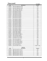
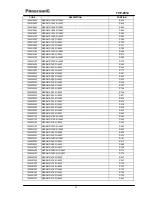
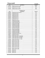
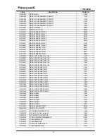
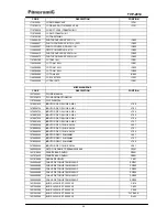
CODE

DESCRIPTION

POSITION

1068101700

ETIQ.NUMERO DE SERIE

1068127201

ETIQ.ADES.N.SERIE C/5

1125707500

PTC B59205-T80-B10 T205 9r+9r

PTC801

1125708600

PTC 96578

PTC801

1161000012

CABO FRAY 2,54 24AWG 5V 520MM

GF501

1161300522

CABO FRAY2,54 2V 24AWG 500MM

GF602

1169200130

FITA 2VIAS 24AWG PR 800MM

GF601

1169200268

CABO FLEX 600V 18AWG MR 420MM

W2

1641000167

CABO MON.1VC/TER.18AWG MR 320

W1

1271206100

RECPETOR IR 36KHZ TSOP34836

RM701

1271205900

RECEPTO IR 36KHZ TSOP1836SS3V3

RM701

1271206300

RECEPTOR IR 36KHZ KSM-602LM2D

RM701

1271505000

SINT 181CH UV1336B/A F S-2 USA

TU101

1312001100

BOBINA LINEARIDADE 34uH

L403

1319953000

INDUTOR 33UH K

L404

1319953000

INDUTOR 33UH K

L805

1319953000

INDUTOR 33UH K

L807

1319955400

FILTRO DE LINHA

T801

1319955400

FILTRO DE LINHA

T802

1319955300

FILTRO DE LINHA ELF18D603NBZ

T801

1319955300

FILTRO DE LINHA ELF18D603NBZ

T802

1319957800

INDUTOR 82uH +/- 10% 2A

L803

1319950500

INDUTOR 120UH +/-10%

L803

1319959300

INDUTOR FIXO 100uH+/-10% 480mA

L400

1353002900

TRAFO DRIVE TD-29B

TF401

1355219099

TRAFO FLY BACK TAT2908B

FLK401

1356006500

TRAFO CHAVEAMENTO ES42307-00

1421506100

RESSONADOR CERAMICO CSB-503F58

X600

1421508300

SAW FILTER M1871M

SF101

1421506200

FILTRO CERAMICO M1967M

SF101

1425008100

CRISTAL 12,000MHZ CL=16pF HC49

X701

1427011200

FERRITE BEAD 2X5X5MM

D807

1427011200

FERRITE BEAD 2X5X5MM

D811

1440090058

CHAVE POWER

SW801

1461058002

FUS. ACAO RET. 20AG 4A/250V

F801

1600005107

PAR.AA.PAN.PH.PP1 3,0X8 ZNA

IC301

1600005107

PAR.AA.PAN.PH.PP1 3,0X8 ZNA

IC601

1631028304

BASE CONECTORA 04VIAS

CN402

1631281402

GUIA P/FIOS 02VIAS

GF601

1631281402

GUIA P/FIOS 02VIAS

GF602

1631281405

GUIA P/FIOS 05VIAS

CN501B

1631281402

GUIA P/FIOS 02VIAS

GF601

1631281402

GUIA P/FIOS 02VIAS

GF602

1631281404

GUIA P/FIOS 04VIAS

GF201A

1631281404

GUIA P/FIOS 04VIAS

GF201B

1631281403

GUIA P/FIOS 03VIAS

GF202A

1631281403

GUIA P/FIOS 03VIAS

GF202B

1631281405

GUIA P/FIOS 05VIAS

CN501A

1631281405

GUIA P/FIOS 05VIAS

1633208600

CONECTOR Y/C S-VHS

SVHS201

1633212303

BASE CONECTORA 03VIAS

CN801

1633212400

CJT.TOMADA 3RCA HT C/CHAVE

Summary of Contents for TVP-2914

Page 1: ...Service Manual Model TVP 2914 CODE 1 01 72434 50...

Page 2: ...CONVERGENCE 18 2 6 VIDEO 19 3 CALIBRATION GUIDE 22 3 1 IMPORTANT RECOMENDATIONS 23 3 2 DEFINITION OF THE REGISTERS 24 3 3 GEOMETRY OF THE IMAGE 27 3 4 WHITE BALANCE 27 3 5 SCREEN ADJUSTMENT 28 3 6 AG...

Page 3: ...1 1 Product Front View 1 1 1 Front Panel Functions and Indications 1 Master 8 Channel 2 Standby 9 Menu 3 Remote control sensor 10 AV 4 Power 11 Video IN 1 5 Volume 12 Audio IN 1 L mono 6 Volume 13 Au...

Page 4: ...o IN AV 2 8 AERIAL Cable b Functions Image Sound Menu Functions Functions Install VHF channel from 2 to13 UHF channel from 14 to 69 Channel Cable TV channel from 1 to 125 c Characteristics Product Dim...

Page 5: ...2914 4 1 3 REMOTE CONTROL 1 3 1 Remote Control Functions 1 Power 9 CC 2 Sleep 10 100 3 AP 11 Menu 4 Volume 12 Volume 5 Channel 13 Channel 6 Numerical keys 14 OSD OUT 7 P Channel 15 AV 8 Stereo SAP 16...

Page 6: ...load and increase volume control until Distortion Meter reading be 10 Measure voltage on the resistive load and calculate power through next equation P V R Where V is voltage in VOLTS R is resistive...

Page 7: ...Readjust the audio generator frequency to 10 kHz at the same level i Read the new voltage Vh at the resistive load and calculate the change in dB through the next equation A 10kHz 20logVH VREF Condit...

Page 8: ...the equate Sep 300Hz L R 20 log VL VR g Adjust the stereo generator for left channel only with 30 modulation of 3kHz sine wave and 7 5 kHz deviation Sep 3kHz L R 20 log VL VR i Repeat the procedures e...

Page 9: ...ated with 400 Hz sine wave and 90 dBuV level d Read the Vam value in the voltmeter AM rejection will now be calculated by the equation RejAM 20 log VFM VAM Note Because this parameter is designed to d...

Page 10: ...4 50 VDC PP 117VAC udio Cathode of D808 20 00 22 00 24 00 VDC PP 117VAC Tuner Cathode of DZ101 30 00 33 00 36 00 VDC PP 117VAC 5V Emitter of Q101 4 50 5 00 5 50 VDC PP 117VAC 3V3 Emitter of Q804 3 00...

Page 11: ...the CRT heat Utilizing a true RMS voltmeter f When exist read the auxiliary wind Peak to peak voltage utilizing an oscilloscope Conition Test Point Minimum Nominal Maximum Unit PP 117VAC 13 00V Catho...

Page 12: ...ferior that shown in the below specific table Condition Minimum Nominal Maximum Unit 1500VAC 3 00 mAAC 2 3 Frame geometric Wide and height of the frame Preparation a Connect the receiver under test to...

Page 13: ...TVP 2914 12 Minimum Nominal Maximum Unit Altura PAL N 12 50 12 80 13 10 Blocks Largura PAL N 16 20 16 50 16 80 Blocks Altura PAL M 12 70 13 00 13 30 Blocks Largura PAL M 16 70 17 00 17 30 Blocks...

Page 14: ...lculate the horizontal centralization a b d c g Observe the image and make the measures in centimeters of the distances p q r and s h Apply the formula to calculate the vertical centralization p q s r...

Page 15: ...odulated PHILIPS pattern Frequency and channel factory defined l c Adjust bright and contrast control to nominal position d For the next reads please take references by figure D e Observe the screen p...

Page 16: ...TVP 2914 15 PAL M Minimum Nominal Maximum Unit DHM 1 10 1 30 DHm 0 70 0 90 PAL N Minimum Nominal Maximum Unit DHM 1 10 1 30 DHm 0 70 0 90...

Page 17: ...on d For the next reads please take references by figure E e Observe the screen pattern and check the distances X in centimeters f Calculate the middle distances through blocks amedium X 11 Major vert...

Page 18: ...his model b Apply to the antenna input a 60dB V level signal with 88 modulated CROSSHATCH pattern Frequency and channel factory defined l c Turn the face tube to West Lest orientation d Adjust bright...

Page 19: ...ain the device 2 5 Convergence a Connect the receiver to a 117VAC line Turn on the TV and adjust bright and contrast control to max position saturation and volume to min position Wait for pre heating...

Page 20: ...z sine wave Frequency and channel factory defined c Connect at the output video detector na AC voltmeter and read the voltage VAC d Turn off the AM modulation and read the noise level Vr AC voltmeter...

Page 21: ...ensibilidade de recep o de Closed Caption a Adjust the TV to a PP condition b Apply a 60dB V signal frequency and channel defined by factory 88 modulated with color bars Pal M with Closed Caption sign...

Page 22: ...e output video detector and read the peak to peak burst level signal Vb c Increment the generator frequency by 500 kHz and read the new value peak to peak burst signal Vh and calculate the percentage...

Page 23: ...rvice key in the service remote control see the description of service remote control b Select the adjustment options pressing the key CH or CH of the remote control of the television front panel or u...

Page 24: ...utes 3 1 2 The positioning of the TV set should obey the magnetic parameters of South America that it is 120 vertical mG In the practice this is gotten with a relative precision positioning the TV set...

Page 25: ...width 34 17 PW 00 63 EW parabola width 35 18 EWUC 00 63 EW upper corner parabola 35 19 EWLC 00 63 EW lower corner parabola 35 20 TC 00 63 EW trapezium 33 21 VSl 00 63 Vertical slope 30 22 VAm 00 63 V...

Page 26: ...SAP noise threshold 8 60 LA 00 15 Input level adjustment 7 61 ALW 00 31 Alignment for wideband 15 62 ALS 00 31 Alignment for spectral 15 Please look the functions of registers bellow before of change...

Page 27: ...no de MAS do tuner est conectado a 5V Register 96 ASTU Register 97 TUNE Value Function Value Function 0 When the MAS pin of the tuner is grounded 0 To TUNER that run with Europe protocol Ex UV1336S A...

Page 28: ...Use the register VSc to adjust Vertical Center Linearity Use the register HSh to adjust Horizontal position 3 4 White balance Note The cut point doesn t need adjustment because it s automatically made...

Page 29: ...Adjust the screen potentiometer to obtain 130V according to the illustration bellow Note The oscilloscope should be positioned in the vertical mode 150 Volts GND Mode 2 a Select the register 99 VSD b...

Page 30: ...5E 470PF 500V K C903 1363471600 C C D Y5P Y5E 470PF 500V K C906 1363471600 C C D Y5P Y5E 470PF 500V K C910 1364104103 C C D Y5V 100KPF 25V Z C306 1364104103 C C D Y5V 100KPF 25V Z C806 1364104102 C C...

Page 31: ...1380229622 ELCO 2 2UF 100V M 5X11MM C610 1380229622 ELCO 2 2UF 100V M 5X11MM C611 1380229622 ELCO 2 2UF 100V M 5X11MM C612 1380229622 ELCO 2 2UF 100V M 5X11MM C616 1380229622 ELCO 2 2UF 100V M 5X11MM...

Page 32: ...5 C627 1494222420 CAP SMD Y5P 220KPF 16V K 0805 C677 1494222420 CAP SMD Y5P 220KPF 16V K 0805 C678 1494222420 CAP SMD Y5P 220KPF 16V K 0805 C730 1494222420 CAP SMD Y5P 220KPF 16V K 0805 R654 149061040...

Page 33: ...MD X7R 220PF 50V K 0603 C675 1492022100 CAP SMD X7R 220PF 50V K 0603 C676 1492022200 CAP SMD X7R 2 2KPF 50V K 0603 C410 1492022200 CAP SMD X7R 2 2KPF 50V K 0603 C615 1492022200 CAP SMD X7R 2 2KPF 50V...

Page 34: ...F 25V M 10X20MM C424 1291102419 ELCO 1000UF 25V M 10X20MM C659 1291102419 ELCO 1000UF 25V M 10X20MM C660 1291102419 ELCO 1000UF 25V M 10X20MM C868 1291220017 ELCO 22UF 250V M 10X20MM C420 1291220017 E...

Page 35: ...ME 1 2W 10K 5 N R828 1183512292 RES METAL FILME 1 2W 1 2K 5 N R112 1183515292 RES METAL FILME 1 2W 1 5K 5 N R308 1183515392 RES METAL FILME 1 2W 15K 5 N R437 1183515492 RES METAL FILME 1 2W 150K 5 N R...

Page 36: ...103 1502510103 RES SMD 100R 5 0603 R104 1502510103 RES SMD 100R 5 0603 R209 1502510103 RES SMD 100R 5 0603 R566 1502510103 RES SMD 100R 5 0603 R605 1502510103 RES SMD 100R 5 0603 R624 1502510203 RES S...

Page 37: ...5 0603 R704 1502522203 RES SMD 2 2K 5 0603 R749 1502522203 RES SMD 2 2K 5 0603 R837 1502522303 RES SMD 22K 5 0603 R406 1502522303 RES SMD 22K 5 0603 R414 1502522303 RES SMD 22K 5 0603 R418 1502522303...

Page 38: ...6 8M K R815 1183556292 RES METAL FILME 1 2W 5 6K 5 N 1183556292 RES METAL FILME 1 2W 5 6K 5 N 1184510025 RES M FILME 2W 10R 5 D KINK R420 1184510025 RES M FILME 2W 10R 5 D KINK R822 1184510045 RES ME...

Page 39: ...C846B Q603 1700100015 TRANSISTOR SMD BC846B Q604 1700100015 TRANSISTOR SMD BC846B Q605 1700100015 TRANSISTOR SMD BC846B Q606 1700100015 TRANSISTOR SMD BC846B Q607 1700100015 TRANSISTOR SMD BC846B Q807...

Page 40: ...RETIFICADOR SK 4F1 06 D409 1415180801 DIODO RETIFICADOR SK 4F1 06 D410 1415180901 DIODO RETIFICADOR SK107 D301 1415180901 DIODO RETIFICADOR SK107 D816 1415180901 DIODO RETIFICADOR SK107 D817 141518090...

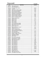
Page 41: ...03 1479906734 INDUTOR FIXO 2 2UH K AXIAL L704 1479907634 INDUTOR FIXO 5 6UH K AXIAL L705 1479907634 INDUTOR FIXO 5 6UH K AXIAL L706 1479907634 INDUTOR FIXO 5 6UH K AXIAL L707 1479908234 INDUTOR FIXO 1...

Page 42: ...120UH 10 L803 1319959300 INDUTOR FIXO 100uH 10 480mA L400 1353002900 TRAFO DRIVE TD 29B TF401 1355219099 TRAFO FLY BACK TAT2908B FLK401 1356006500 TRAFO CHAVEAMENTO ES42307 00 1421506100 RESSONADOR C...

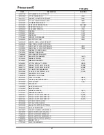
Page 43: ...H1 1510454007 ALTO FALANTE 2x5 7 10W 8R 9 2G5 1600015112 PAR AA P PH PP1 4 0X12 ZNA RES 22 8G5 1600015114 PAR AA P PH PP1 4 0X20 ZNA RES 22 8G5 1408011900 CJT CINESCOPIO A68AJB82X03 8 F5 1607316362 P...

Page 44: ...MOLA DE CONTATO PILHA NEG 1687218502 MOLA DE CONTATO PILHA POS 1687218503 MOLA CONTATO PILHA POS NEG 1600059545 PAR AA BIND PH PP1 2 0X6 ZNP 1600005502 PAR AA PAN PH PP1 2 0X5 ZNP 1027222023 CJT PCI...

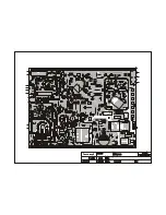
Page 45: ...TVP 2914 44 5 ELECTRICAL SCHEME 5 1 MAIN AND REMOTE CONTROL PCB 6 SILKTOPS AND SOLDERS 6 1 MAIN PCB 6 2 REMOTE CONTROL PCB 7 EXPLODED VIEW 8 BLOCK DIAGRAM...

Page 46: ...0R 47uF 25V 47R 3 2 1 8K2 10uF 50V SK4F1 06 4 7uF 100V SK 3G08 SK 3G08 470uF 25V 560R 100R 100R 1K5 100R BC856B 0 SERVICE 470PF 500V TDA9855 BZX79C18 27K 100R 100KpF 16V 22K 8K2 15uH BC846B TPS4M50C00...

Page 47: ...C660 JD11 R854 R304 C812 JD12 R630 FR431 R423 D409 FR419 FR423 C407 R825 Q805 E B C C852 JC21 DZ808 3V3 DZ809 8V2 JF7 JG8 C659 GF201B 4 1 C841 DZ811 10V R820 JF9 C720 JC45 C867 JC20 C302 JD7 C816 CN5...

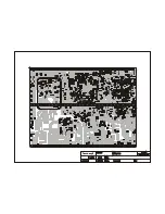
Page 48: ...56 R845 R848 R836 Q703 C E B R723 C691 C721 R628 C711 C712 R212 C205 R406 C730 C105 C410 75 70 65 64 60 55 50 45 41 40 35 30 25 24 20 15 10 5 1 C413 C305 C307 C760 R660 R301 R302 C662 C663 C667 C669 C...

Page 49: ...mm REMOTE CONTROL PCB NOME DATA MAT APRO 15 08 00 N PROJ DES 15 08 00 ACAB ESC MOD TOL 15 08 00 TVP 2914 IC1 X1 C1 C B E LD1 29 10 02 72220 30 MUTE POWER AP SLEEP AV OSD OUT V V CH CH MENU 1 2 3 6 5 4...

Page 50: ...T TULO PROJE O dimens es em mm REMOTE CONTROL PCB NOME DATA MAT APRO 15 08 00 N PROJ DES 15 08 00 ACAB ESC MOD TOL 15 08 00 TVP 2914 10 1 R2 1 10 11 20 C3 Q1 R1 C4...

Page 51: ......
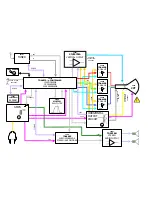
Page 52: ...AKB 205V 15V V901 CPT IC701 CAT24WC08J EEPROM I C BUS I C BUS IC901 TDA6106 RGB AMP AKB IC901 TDA6106 RGB AMP AKB IC901 TDA6106 RGB AMP AKB HORIZONTAL OUTPUT CIRCUIT 50V IC601 TA8216H STEREO AUDIO OUT...

Reviews: