background image

G510 Service Manual                                                                                                            G510 


G510 Service Manual 

(GSM Cellular Phone) 


Pantech  Co., Ltd., Korea


September 5, 2003 

1

st

 Edition  


For Use by Authorized Service/Maintenance Personal Only 

Documents to Receive This Addendum: 

G510 Maintenance/Repair/Operating Manual 

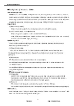
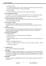
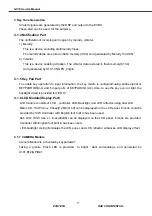
Summary of Contents for G510

Page 1: ...0 G510 Service Manual GSM Cellular Phone Pantech Co Ltd Korea September 5 2003 1st Edition For Use by Authorized Service Maintenance Personal Only Documents to Receive This Addendum G510 Maintenance R...

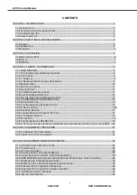
Page 2: ...N 14 4 2 3 1 AN OVERVIEW OF RECEIVE SECTION 14 4 2 3 2 RECEIVER PART 155 4 2 4 TRANSMIT SECTION 17 4 2 4 1 AN OVERVIEW OF TRANSMIT SECTION 17 4 2 4 2 TRANSMITTER PART 18 4 2 5 OFFSET PLL 19 4 2 5 1 AN...

Page 3: ...ATOR NOT WORKING 36 6 3 SIM CARD PART 37 6 3 1 SIM ERROR 37 6 4 CHARGER PART 38 6 4 1 CHARGING ERROR 38 6 5 RF PART 40 6 5 1 TEST CONDITIONS 40 6 5 2 POWER SUPPLY CHECK POINT 41 6 5 3 POWER AMPLIFIER...

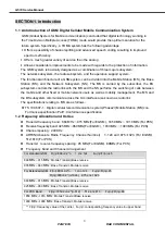
Page 4: ...xed or mobile network users as well as mobility management The MS and the BS subsystem communicate across the Um interface also known as radio link The specifications relating to MS are as follows TS...

Page 5: ...e used appropriately to ensure its best performance This product consists of a handset battery pack and Travel charger 1 4 Characteristics 1 All the active devices of G510 are made of semiconductors t...

Page 6: ...3 2 30 2 dBm Frequency Error 90Hz 180Hz Phase Error RMS 5 PEAK 20 Minimum Output Power 5 5 0 5 dBm Power Control 5 19 2 dB Step 0 15 2 dB Step Output RF Spectrum TS 100 910V6 2 0 Switching Transient T...

Page 7: ...G510 Service Manual PANTECH R D CONFIDENTIAL 6 Section 3 Operation 3 1 Name of each part Sub LCD Display Screen Antenna Speaker Earpiece Navigation Key Flash LED Camera MIC Camera Key...

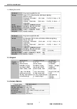
Page 8: ...haracter font size 16 16 1 lines 6 characters Model COM18T1188DEB CASIO Module Dimen 36 5 W x 55 1 H x 5 1 D mm Effective Area 23 04 W x 23 04 H mm 1 3 inch Number of Dots 128 W x RGB W x 128 H dot Do...

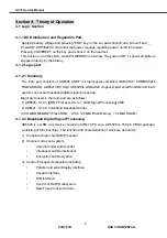
Page 9: ...is GSM ASIC chipset implemented for GSM terminal s system control and baseband digital signal processing Major parts used in the logic part are as follows 1 AD6526 U101 ARM7 Processor Core GSM Signal...

Page 10: ...as follows 1 Speech transcoding In full rate the DSP receives the speech data stream from VBC and encodes data from 104kbps to13kbps Using algorithm is Regular Pulse Excitation with Long Term Predict...

Page 11: ...Speech Transcoding In full rate mode the DSP receive the speech data stream from the VBC and encodes data from 104kbps to 13kbps Using algorithm is Regular Pulse Exitation with Long Term Prediction a...

Page 12: ...d using strobe signal of KEYPADROW 0 4 and 5 input ports of KEYPADCOL 0 4 Also to use the key even at light the backlight circuit is provided for LED 13 4 1 6 LCD Module Display Part LCD module consis...

Page 13: ...architecture that avoids the difficulties associated with direct conversion while delivering lower solution cost and reduced complexity The transmit section is a complete up conversion path from the b...

Page 14: ...ge in return is applied to the logic part and RF part via LDO Low Drop Out regulator As several LDO regulators are used power can be supplied for each necessary part efficiently Audio Logic parts use...

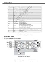
Page 15: ...G510 Service Manual PANTECH R D CONFIDENTIAL 14 Table 4 1 Pin Description of Si4200DB BM 4 2 3 Receiver Section 4 2 3 1 An Overview of Receive section Fig 4 6 Receiver block diagram...

Page 16: ...is internally divided by 2 for GSM 850 and E GSM 900 modes The mixer output is amplified with an analog programmable gain amplifier PGA which is controlled with the AGAIN bits in register 05h The qua...

Page 17: ...he power amplifier and transmits it to the antenna The maximum insertion loss is about 0 8 dB for the receiving bands at 25o C and about 1 35 dB for the transmitting bands at 25o C B SAW filter BPF Ba...

Page 18: ...hat is filtered and used as the reference input to the OPLL The IFLO frequency is generated between 766 and 896 MHz and internally divided by 2 to generate the quadrature LO signals for the quadrature...

Page 19: ...ies when the terminal transmits GMSK modulated frequencies C Power AMP Module PAM Z710 This device amplifies signals ahead of transmiting them through the antenna to provide a sufficient RF power It h...

Page 20: ...mode All VCO tuning inductors are also integrated The IF and RF output frequencies are set by programming the N Divider registers NRF1 NRF2 and NIF Programming the N Divider register for either RF1 o...

Page 21: ...e Controlled Temperature Compensated Crystal Oscillator V801 This is the mobile station s reference frequency source Its frequency is 13MHz this signal is applied to Si4205 U710 _pin8 AD6526 U101 and...

Page 22: ...n Test Set Agilent Technologies 8593E Spectrum Analyzer Hewlett Packard TDS 340A Oscilloscope Tektronix FLUKE 87 Digital Multimeter Fluke E3630A DC Power Supply Hewlett Packard Others Accessory Interf...

Page 23: ...L 22 SECTION 6 Equipment Repair Procedure 6 1 No Power On with battery Applied 6 1 1 Power CHECK 1 Check battery power 3 5V 4 2V BATTERY PACK 2 Check to see if U103 22 19 2 pin voltage is same with ba...

Page 24: ...G510 Service Manual PANTECH R D CONFIDENTIAL 23 3 Check to see if Q101 7 8 and 9 pin is same with battery power CP101 4 Check to see if U113 1 pin is same with battery power CP102 CP101 CP101 CP102...

Page 25: ...PANTECH R D CONFIDENTIAL 24 5 Check to see if U103 21 20 23 and 3 pin is 1 8V 2 8V 2 55V_A 1 95V_RTC CP103 6 Check to see if U103 30 pin becomes to 0V CP104 Pressing END key to turn on equipment CP10...

Page 26: ...G510 Service Manual PANTECH R D CONFIDENTIAL 25 7 Check to see if C106 109 C111 C114 C100 103 is 2 8V_M 1 8V_D CP105 CP104 CP105 CP105...

Page 27: ...D CONFIDENTIAL 26 8 Check to see if U106 5 pin and J103 28 pin is 2 8V_EXT CP107 6 1 2 Oscillation CHECK 1 Check to see if U101 No A3 and B3 pin is oscillated 32 768KHz CP108 2 NO Check R138 and then...

Page 28: ...heck to see if R129 1 pin is around 2 8V duty 80 256Hz CP110 NO Check R129 and Q102 and then replace those 2 Check to see if R123 124 125 126 127 128 is same with battery voltage CP111 NO Check the PC...

Page 29: ...G510 Service Manual PANTECH R D CONFIDENTIAL 28 CP111 CP112 CP110 CP111 CP112...

Page 30: ...Hands free Mic 6 2 1 No receiving tone heard Ear piece 1 Check to see if U102 Nos F10 A9 and J8 C118 C119 C120 is 2 55V_A CP118 2 Check to see if U102 No A7 C124 is around 1 2V CP119 Set to HP8922M t...

Page 31: ...to see if U102 Nos F10 A9 and J8 C118 C119 C120 is 2 55V_A CP118 2 Check to see if 102 No A7 C124 is around 1 2V CP119 3 Check to see if U101 No B11 D124 is around 0V CP123 NO Check to see J106 CP124...

Page 32: ...G510 Service Manual PANTECH R D CONFIDENTIAL 31 CP124 CP120 CP123 CP118 CP124 CP119 CP123...

Page 33: ...o 1Khz with Echo audio mode 2 Check U102 No J10 C132 pins for wave form CP127 NO Replace MIC 6 2 4 Side Tone Not transmitted Hands free Mic Repeat 6 2 2 No receiving tone heard Hands free Earphone 1 C...

Page 34: ...heck to see if U111 No 3 is around 0 15V CP132 NO Check that R109 and R110 cold solder broken short to the other PCB pattern or not If you find out any defect you replace it 4 Check to see if U111 No...

Page 35: ...if U105 15 is Vbat CP135 3 Check U105 Nos 12 13 and 14 pin for wave form CP136 NO Check that R175 R177 R31 C196 C197 cold solder broken short to the other PCB pattern or not If you find out any defec...

Page 36: ...G510 Service Manual PANTECH R D CONFIDENTIAL 35 CP134 CP135 CP136 CP137 CP134 CP135 CP136 CP137 CP136 CP134 CP135...

Page 37: ...older broken short to the other PCB pattern or not If you find out any defect you replace it 2 Check to see J103 11 is same with battery power CP138 CP139 NO Check to see R160 cold solder broken short...

Page 38: ...see U103 18 pin cold solder broken short to the other PCB pattern or not CP141 If you find out any defect you replace it 2 Check to see J103 JST 2 3 6 for wave form CP142 NO Check to see J103 JST R133...

Page 39: ...ther PCB pattern or not CP144 If you find out any defect you replace it 2 Check to see U103 14 pin is low 0V CP145 NO Check to see U103 cold solder broken short to the other PCB pattern or not If you...

Page 40: ...G510 Service Manual PANTECH R D CONFIDENTIAL 39 CP145 CP143 CP146 CP144...

Page 41: ...tion 2 Traffic channel EGSM Band Tx mode Ch62 Power Level 13 3 Test condition 3 Traffic channel PCS Band Tx mode Ch6662 Power Level 10 4 Test condition 4 Traffic channel GSM Band Rx mode Ch62 Input po...

Page 42: ...U907 Pin 1 3 8V 2 3 4 5 Check route connection VBAT 2 2 U907 Pin 5 2 8V 2 3 4 5 Check route connection VBAT 2 3 U701 Pin 4 3 8V 2 3 4 5 Check route connection VBAT 2 4 U701 Pin 5 2 8V 2 3 4 5 Check r...

Page 43: ...G510 Service Manual PANTECH R D CONFIDENTIAL 42 Fig 6 3 Z710 PAM s Power Check Point Fig 6 4 Z710 PAM s PCB Layout...

Page 44: ...en you can trace the guideline of PAM as follows Step Test point Typical Value Condition Checking Point 3 1 Z710 Pin 3 Logic High 2 3 Check route connection TXEN Logic High 3 5 3 2 Z710 Pin 2 Logic Lo...

Page 45: ...G510 Service Manual PANTECH R D CONFIDENTIAL 44 STEP 3 2 Fig 6 6 PAM PCSSEL Test Point Circuit Fig 6 7 PAM TXEN and PCSSEL Test Point on the PCB Layout...

Page 46: ...ep Test point Typical Value Condition Reaction to Abnormality 4 1 V801 Pin 1 0 5V 2 5V 2 3 4 5 Check route connection AFC 4 2 V801 Pin 4 2 8V 2 3 4 5 Check route connection VTCXO Fig 6 8 VCTCXO Check...

Page 47: ...Condition Check point 5 1 Z701 Pin 11 2 6V 2 5 2 Z701 Pin 2 2 6V 3 When Pin 11 is Logic High and Pin 2 is Logic Low the mode is EGSM band While Pin 2 is Logic High and Pin 11 is Logic Low the operati...

Page 48: ...RF exposure FCC For body worn operation to maintain compliance with FCC RF exposure guidelines use only accessories that contain no metallic components and provide a separation distance of 15mm 0 6 i...

Reviews: