G510 Service Manual
PANTECH
R&D
CONFIDENTIAL
15
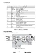
G510’s Aero I transceiver uses a low-IF receiver architecture which allows for the on-chip
integration of the channel selection filters, eliminating the external RF image reject filters and the IF
SAW filter required in conventional superheterodyne architectures. Compared to a
direct-conversion architecture, the low-IF architecture has a much greater degree of immunity to dc
offsets, which can arise from RF local oscillator (RFLO) self-mixing, 2nd-order distortion of blockers,
and device 1/f noise. This relaxes the common-mode balance requirements on the input SAW filters,
and simplifies PC board design and manufacturing.
Three differential-input LNAs are integrated on the Aero I transceiver. The GSM input supports the
GSM 850 (869–894 MHz) or EGSM 900 (925–960 MHz) bands. The PCS input supports the PCS
1900 (1930–1990 MHz) band. The PCS input supports the PCS 1900 (1930–1990 MHz) band.
G510 use only two inputs that are GSM and PCS inputs.
The LNA inputs are matched to the 150
Ω
balancedoutput SAW filters through external LC
matching networks. The LNA gain is controlled with the LNAG and LNAC bits.
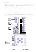
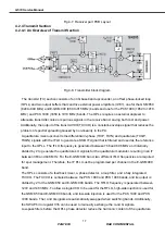
A quadrature image-reject mixer downconverts the RF signal to a 100 kHz intermediate frequency
(IF) with the RFLO from the frequency synthesizer. The RFLO frequency is between 1737.8 to
1989.9 MHz, and is internally divided by 2 for GSM 850 and E-GSM 900 modes. The mixer output is
amplified with an analog programmable gain amplifier (PGA), which is controlled with the AGAIN
bits in register 05h. The quadrature IF signal is digitized with high resolution A/D converters
(APCS).
The ADC output is downconverted to baseband with a digital 100 kHz quadrature LO signal. Digital
decimation and IIR filters perform channel selection to remove blocking and reference interference
signals. The response of the IIR filter is programmable to a high selectivity setting or a low
selectivity setting. The low selectivity filter has a flatter group delay response which may be
desirable where the final channelization filter is in the baseband chip. After channel selection, the
digital output is scaled with a digital PGA, which is controlled with the DGAIN bits.
The LNAG, LNAC, AGAIN and DGAIN bits must be set to provide a constant amplitude signal to the
baseband receive inputs.
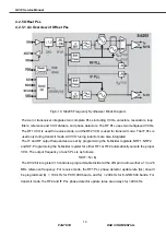
DACs drive a differential analog signal onto the RXIP, RXIN, RXQP, and RXQN pins to interface to
standard analog-input baseband ICs. No special processing is required in the baseband for offset
compensation or extended dynamic range. The receive and transmit baseband I/Q pins can be
multiplexed together into a 4-wire interface. The common mode level at the receive I and Q outputs
is programmable, and the full scale level is also programmable.
4.2.3.2 Receiver Part
A. Diplexer: Z701
Diplexer consists of Tx filter, having an antenna port, and dual configuration with the transmitting

