background image

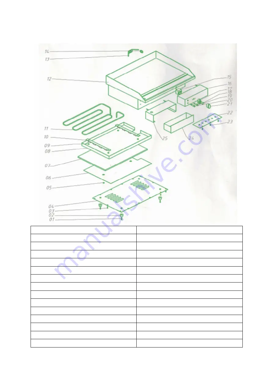
Parts Diagram


No. 

Description 

Bolt (foot) 

Rubber (foot) 

Screw (base) 

Bottom Plate 

Nut 

Outer Plate 


Inner Plate 

Nut 

10 

Element Support 

11 

Element 

12 

Body Shell 

13 

Plug & Mains Cable 

14 

Cable Gland 

Summary of Contents for G1

Page 1: ...Griddle G1 Operating Manual ...

Page 2: ...f the supply The machine must be earthed when used There is a danger of electric shock if it is not earthed In case of emergency please turn off the power switch and unplug the machine If the electric wire becomes damaged a qualified engineer or the manufacturer must replace it Pantheon Catering Equipment is not responsible for any accidents or faults caused by amendments made to the machine or im...

Page 3: ...erature reaches the set temperature the thermostat switches off the heat and the yellow indicator goes out 4 When the temperature drops below the temperature that has been set the thermostat switches the heat on again 5 This process repeats in order to maintain the required temperature 6 Adjust the temperature control dependent on the type of food being cooked in order to get the best results 7 Wh...

Page 4: ...e cannot be adjusted 1 The connection of the yellow indicator is damaged 2 The thermostat is broken 1 Check the wiring for the yellow indicator 2 Replace the thermostat The yellow indicator is not illuminated but temperature control functions normally 1 The contact for the indicator is not functioning 2 The indicator is burned out 1 Check the connection 2 Replace the indicator Circuit Diagram ST T...

Page 5: ...arts Diagram No Description 1 Bolt foot 2 Rubber foot 3 Screw base 4 Bottom Plate 5 Nut 6 Outer Plate 7 8 Inner Plate 9 Nut 10 Element Support 11 Element 12 Body Shell 13 Plug Mains Cable 14 Cable Gland ...

Page 6: ...15 Thermostat 16 Front Cover 17 Bezzel for Temperature Knob 18 Screws 19 Indicator 20 Indicator 21 Control Knob 22 Bottom Panel for Electric Box 23 Screws 24 Drip Tray 25 Drip Tray Housing ...

Reviews: