background image

7

4.

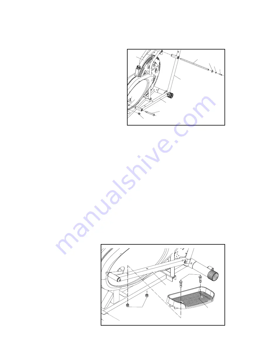
 . .Attach .right .

Pedal 

(#11)

 .to .

Right Pedal 

Tubing (#6R).

 .

Use .two .

3/8” x17/8” 

Bolts (#44)

 .and .

two .

3/8” Nuts (#45).

 .

Repeat .these .steps .on .
left .side . .(See .Fig .3)

NOTE: 

Use .WD40 .or .any .tool .lubricant .to .reduce .friction .when .screwing .in .the .

Pedal Hinge Bolt

 .to .the .

Crankshaft.

 .The .bolt .may .become .tight .at .times .and .

may .even .feel .like .it .will .no .longer .screw .in . .However, .making .sure .screw .is .
properly .lubricated .and .performing .occasional .back .and .forth .twists .to .the .bolt .
will .ensure .that .it .goes .through .with .more .ease . .

NOTE:

 .Both .

Pedal Hinge Bolts 

will .not .have .the .same .screw .pattern .and .both .the .left .and .right .sides .will .tighten .
using .opposite .tightening .directions .

2.

 . .Insert .the .

Handle Bar Shaft (#12A) 

through .the .

Coupler Bar

 .of .either .the

right .or .left .side . .Making .sure .the .

Handle Bar Shaft (#12A)

 .goes .

all .the .way .through .the .main .
frame .and .reaches .the .outer .end .
of .opposite .

Coupler Bar. 

Make .

sure .to .secure .

Handle Bar Shaft

 .

by .using .the .

Hinge Screw (#57), 

Sharp Washer (#49)

 .and .

Spring 

Washer (#52)

 .by .tightening .

the .

Hinge Screw

 .at .each .end .

simultaneously .with .the .2 .

Small 

Allen Keys

 .provided . .

3.

 . .Now .to .complete .assembly .of .the .arm .bar, .insert .a .

Pedal Hinge Bolt (#12B)

 .

through .the .

Pedal Tubing (#6R for right side, #6L for left side).

 .Screw .the .

Pedal Hinge Bolt

 .using .the .

Large Allen Key

 .provided, .into .the .

Crankshaft, 

which .is .already .installed .within .the .Panther’s .main .frame . .Secure .the .

Pedal 

Hinge Bolt

 .at .the .inner .end .with .a .½” .

Spring Nut (#48)

 .and .a .½” .

Spring  

Washer (#51).

 .(See .Fig .2)

Steps 2 through 4


will .detail .assembly .of .

Pedals 

and

 Coupler Bars

 . .Repeat .these .

steps .on .each .side .(Left .and .Right) .before .moving .on .to .Handle .Bar .assembly .

Fig 3

44

6

45

11

Fig 2

27

12B

48

51

6R

4

12A

49

57

52

1

Summary of Contents for Elliptical

Page 1: ...Panther_BilingualMAN_TP_ENG SPAN_V1_110802 ...

Page 2: ......

Page 3: ...e Starting 5 Hardware Provided 5 Assembling 6 Handle Bars 8 Digital Monitor 8 Adjusting Resistance 9 Dual Movement 9 Exploded Diagram Parts List 10 IMPORTANT Please read all instructions carefully before using this product Retain this manual for future reference ...

Page 4: ...ly in the way described in this manual Any unauthorized accessories or add ons should not be used at any time 7 When operating make sure NOT to place any sharp objects around the Panther Elliptical 8 It is strongly suggested that any disabled users NOT use the Panther Elliptical without the supervision of a health professional or physician 9 Make sure to always stretch and warm up properly before ...

Page 5: ...ing tools to assemble the Panther Elliptical Adjustable wrench Standard screwdriver WD40 or spray lubricant 2 small Allen keys 1 large Allen key provided 3 Please make sure to understand all safety precautions prior to assembly II Hardware Provided Organize your bolts and nuts according to the below illustration prior to assembly Nuts and bolts are identified by their size For more information ref...

Page 6: ...o the Main Frame 1 using two 3 8 x60 Carriage Bolts 46 and two 3 8 Acorn Nuts 47 See Fig 1 The Front Base 2 has wheels for transporting your Panther 3 Rear Cylindrical Base 47 3 8 Acorn Nut 46B Washer M10 1 Main Frame 46 3 8 x60 Carriage Bolt 2 Front Cylindrical Base with Wheels FRONT REAR Fig 1 ...

Page 7: ...ht or left side Making sure the Handle Bar Shaft 12A goes all the way through the main frame and reaches the outer end of opposite Coupler Bar Make sure to secure Handle Bar Shaft by using the Hinge Screw 57 Sharp Washer 49 and Spring Washer 52 by tightening the Hinge Screw at each end simultaneously with the 2 Small Allen Keys provided 3 Now to complete assembly of the arm bar insert a Pedal Hing...

Page 8: ...action mode it is important to select a height setting that is most comfortable for you and always place both Handle Bars at the same height Once you decide on the most comfortable height use two Knob Bolts 17 to secure Handle Bars in place See Fig 4 7L Fig 4 17 5 V Digital Monitor 7 Slide the Digital Monitor 50 into the bracket welded on the Main Frame Connect the Monitor to the sensor wire attac...

Page 9: ... the Main Frame The tighter the Tension Belt is strapped around the wheel the higher the resistance and the more intense your workout will become Please make sure to readjust the Resistance Knob after adjusting the tension belt VI Dual Movement Keep in mind that your Panther Elliptical features DUAL Movement Forward and backward motion Forward pedaling reinforces your quadriceps muscles while back...

Page 10: ... 22 Fan wheel axle 1 23 Nut M10 3 24 AL belt 1 25 Nut M10 2 26 Sensor 1 27 Crankshaft 1 28 Chain Wheel 1 29 W S OD40 5xID24 1 30R Collar Housing 1 30L Collar Housing 1 31 Collar ball 2 32 Collar Housing 2 33 Nut M22 1 34 Chain 25H 220L 1 35 Tension Belt 1 36 Resistance Knob 1 37 Tension Spring 1 38 Chain cover screw M5 15 2 39 Chain cover screw M5 45L 6 Part No Description Qty 40 Tension fix screw...

Reviews: