background image

INTRODUCTION

Any angler who trolls with a kicker motor will appreciate the benefits of the Panther T‐4 Electrosteer.  
Installs easily on any kicker motor that has a threaded  lt‐tube, and there is no need to drill holes in your 
transom. The drive unit has a rugged internal motor that steers the kicker though the use of a remote 
tethered to a 24 foot cable. Simply push one of the direc onal bu ons and the T‐4 will immediately 
respond, moving your kicker incrementally for precision control. For a drama c move, hold down the bu on 
to quickly move your kicker from full right to le  in seconds to swi ly and safely make a hard turn. The drive 
unit and remote are powered by your boat’s 12 volt ba ery . 

NOTE: The T‐4 CANNOT be used if you have a main engine to kicker steering  e bar.  The main engine  e 
bar must be disconnected. 

Please take a few moments to review the informa on contained in this booklet to familiarize yourself with 
the installa on procedures of your new 

T‐4.  

Installa on is easy par cularly when you know each step 

ahead of  me. 

GETTING STARTED

Here is a list of the tools and supplies that you may need: 

Tools and Equipment:


1. Electric drill with 1/8 drill bit
2. A Phillips head screw driver
3. Tube of dielectric grease for the electrical connec ons (recommended)
4. 1 1/4” Wrench or equivalent tool
5. Hacksaw

NOTE: 

DO NOT CUT THE ROD UNTIL ALL THE DIRECTIONS HAVE BEEN 

READ AND YOU ARE SURE OF THE ROD LENGTH 

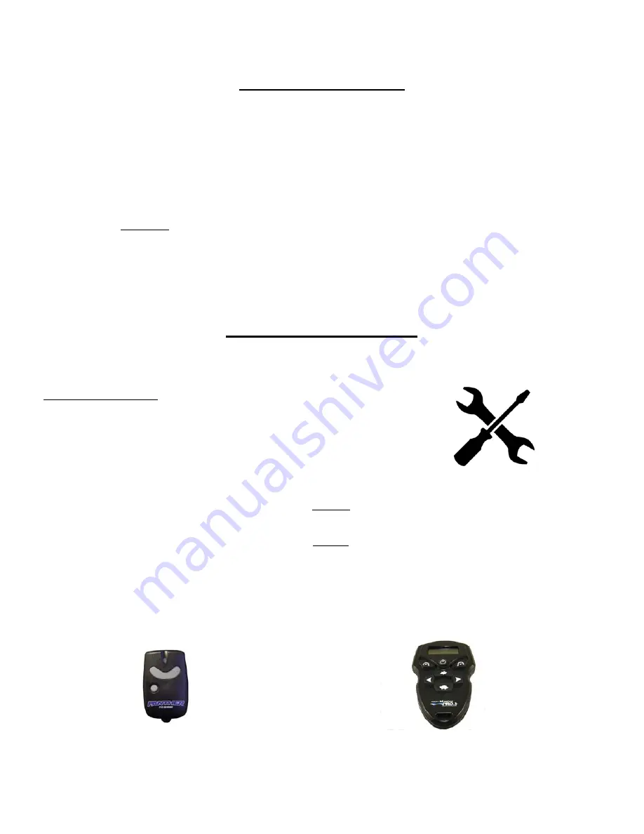
The Panther T‐4 is controlled with a push bu on switch on a 24 foot cable.  It can also be controlled 
using the op onal Wireless Remote [Panther part # 55‐0105], or the TrollMaster PRO3 Plus wireless 
thro le and steering control [TMPRO3PLUS].  Both sold separately.  

PANTHER WIRELESS REMOTE 

TROLL MASTER  PRO 3 PLUS 

Summary of Contents for Freshwater 55-0102

Page 1: ...M 55 0102 M 55 0103 S T 4 ELECTROSTEER INSTALLATION AND OPERATING INSTRUCTIONS CUSTOMER MUST RECEIVE THIS MANUAL AT TIME OF SALE OR AFTER INSTALLATION Rev 1 17 P N 99 55286 ...

Page 2: ...ker steering e bar The main engine e bar must be disconnected Please take a few moments to review the informa on contained in this booklet to familiarize yourself with the installa on procedures of your new T 4 Installa on is easy par cularly when you know each step ahead of me GETTING STARTED Here is a list of the tools and supplies that you may need Tools and Equipment 1 Electric drill with 1 8 ...

Page 3: ...for the control module to the T 4 unit 4 Apply a small amount of dielectric grease to each of the connectors and plug them together 5 A er all connec ons are made connect the ring terminal leads to the ba ery Connect the red lead to the posi ve terminal and the black lead to the nega ve terminal 6 Test the unit by running it back and forth to make sure that there is adequate slack in the wiring ha...

Page 4: ... directly in front of the motor cover to determine where is the best place for you to drill a hole The ball stud can be installed with the ball up or down The only concern is that you need to have enough room to a ach the quick disconnect over the ball stud Be certain you are not drilling into anywhere that has wiring routed through it See pictures 3 4 55 5705 op onal bracket is used in pictures 3...

Page 5: ...n some cases you will always have more threads on the lt tube In that case place one or more supplied nylon spacer spacers on the lt tube to make up the difference and then adjust the nut on the T 4 accordingly Picture 2 3 When Step 2 is done place the T 4 onto the lt tube opposite the drive rod and push the T 4 body toward the motor while turning the nut clockwise The T 4 body will automa cally gh...

Page 6: ...od Make note of this measurement and add 1 7 Cut the rod and a ach the other jam nut and quick disconnect 8 Place the quick disconnect over the ball stud on the drive rod If the connec ng rod assembly is s ll too long slightly loosening the drive rod no more than one full turn may resolve the issue Otherwise re measure and cut again to get the proper length 9 Press the push bu on Check for any bin...

Page 7: ... addi onal ball stud and mount it on your transom deck A ach the loose end that you have disconnected from the kicker to the ball stud mounted on the transom WARNING NEVER STAND ON OR PUT DOWNWARD PRESSURE ON THE T 4 BODY IT CANNOT BE USED AS A STEP OR RESTING PLACE FOR YOUR FOOT WHILE FISHING MAINTENANCE The following is a list of items to do periodically to insure the longevity of your T 4 1 Fre...

Page 8: ...he transmi er to the receiver A disconnect power to receiver either posi ve or nega ve terminal B Enable the transmi er by pressing the power bu on the LED will flash twice C Hold down either direc onal bu on on the transmi er D While holding down bu on connect power for about one second E You should hear a relay on the receiver click F Release bu on and fully reconnect power G Your transmi er is n...

Page 9: ...oes not apply if the unit has been damaged by accident abuse misuse poor installa on or misapplica on or if it has been modified from its original condi on or if any serial number has been removed or defaced or altered This warranty does not cover any expense to remove or reinstall the unit or any of its components If a returned unit is not covered by warranty the sender will be no fied and given an...

Reviews: