
128-9108
1 of 24
Page 1
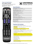
Model PA-620C
Installation Manual
This Remote Start System is designed to be used with
Automatic Transmission-Fuel Injection Vehicles Only!
COMPONENTS:
Control Module
2 Four Button RF Transmitters
Antenna/Receiver
1 1” X 1.75” Foam Pad
6 Pin Main Power Harness
7 Pin Accessory Harness
1 Hood Pin Switch
5 Pin Receiver Harness
3 Pin Parking Light/Ground Harness
2 Door Lock Harness
4 Pin Auxiliary Output Harness
DBI Port For Data Bus Module Applications
Installation/Owners Guide
FEATURES:
* Selectable Ignition Lock and Unlock
* Selectable Door Lock/Unlock Output Timing
* Safe Start (Requires double push of the start button to engage the remote start function)
* On Board Parking Light Relay
* Trunk Release Output
* Horn Chirp Output With Selectable Duration
* Selectable RF Start Chirp
* Car Finder Mode (Can elect to have horn beep along with parking lights if connected)
* Selectable Run Times 5, 10, 15, or 20 Minutes
* Selectable Gas or Diesel
* Pathway Illumination Selectable On Arm, On Disarm, On Both or Off
* Automatic Start Timer
(Can be set to start your car automatically at 2 or 4 hour intervals)
* 4 Negative Pulsed Aux Outputs Before Start, After Start, During Crank, After Shut Down
(To aid installation in many vehicles with factory alarm systems)
FCC NOTICE
This device complies with part 15 of the FCC rules. Operation of this device is subject to the following
conditions:
(1) This device may not cause harmful interference, and
(2) This device must accept any interference received, including interference that may cause undesired
operation.
Caution: Changes or modifications not expressly approved by the party responsible for compliance voids the
users authority to operate this device.
Summary of Contents for PA-620C
Page 5: ...128 9108 5 of 24 Page 5 ...